1. Applications
The electronic floor temperature controller is used for
controlling electric:
• direct floor heating
• floor temperature conditioning systems
Features
• Nighttime set-back, input for external clock
• Indicator lamps for "controller calls for heat" and for
set-back operation
• 2-pole mains switch
• Mounting in 55mm appliance socket
2. Description of functions
2.1 Functions
The floor temperature is set via the dial and is measured
by the remote sensor.
The scale of *…4 corresponds to a temperature of
10…40 °C.
Note: After switching on power supply, it may take some
time until an acceptable control quality will be
achieved.
Lamps
Red: Controller calls for heat
Green: Set-back mode is activated
2.2 Functions of the set-back input TA
èè
The TA input is used to set the thermostat into the ener-
gy saving mode (by using an external timer).
In this mode, the room temperature will be reduced by
3°C or 5°C (depending on jumper J2).
Caution-1!
The device may only be opened and installed ac-
cording to the circuit diagram on the device or these
instructions by a qualified electrician. The existing
safety regulations must be observed.
In order to comply with safety class II, the necessary
installation steps must be taken.
This independently mountable electronic device is de-
signed for controlling the temperature in dry and en-
closed rooms only under normal conditions. The devi-
ce confirms to EN 60730, it works according operating
principle 1C
468 931 003 295-1
╞
Instructions for use
and assembly
Electronic floor temperature controller
with set-back input
FTE 5050 SN
2.3 Selecting the set-back temperature
By means of the J2 jumper it is possible to select 3°
or 5°.
J2 closed set-back by 5°C (factory pre-set)
J2 open set-back by 3°C
The temperature set externally via the dial is reduced by
this value.
2.4 Fault of the floor sensor
If a sensor fault (short-circuit or break) occurs, the con-
troller will switch to fault mode. The heating will func-
tion with max. 30 % of the energy (operation for 30 % of
the time). This provides frost- and overheat protection.
In the event of a sensor fault, both lamps will flash.
2.5 Function of the lamps
Function Lamp green Lamp red
Heating is on on
Set-back mode on
Floor sensor fault flashes flashes
3. Electrical connection
Perform the steps described below:
• Pull off the temperature dial
• Release the fixing screw
• Remove the upper part of the casing
• Connect acc. to circuit diagram (see bottom of casing)
Floor sensor
The remote sensor must be mounted in such a way that
the temperature to be limited can be correctly re-
corded.
The remote sensor should be installed in a protective
tube. This will facilitate future replacement.
Do not install the sensor close to power lines. In other
cases a shilded cable has to be used.
The sensor can be extended to max. 50 m by means of
a cable suitable for mains voltage.
Caution!
The sensor lines are on mains voltage (230 V).
4. Technical data
Order designation FTE 5050 SN
Temperature setting range:
Floor temperature *…4 (= 10…40ºC)
Indicator lamp red Controller calls for heat
green Set-back temperature
Power switch 2-pole
Supply voltage 230 V AC (195…253 V) 50 Hz
Output Relay make contact
Switching current 100 mA…16 A cosϕ = 1;
100mA… 2A cosϕ = 0.6
Control algorithm Proportional controller
(similar to continuous
through PWM)
Switching temperature
differential ~1°C
Floor sensor Length 4 m,
can be extended to max. 50 m
Temperature set-back 3K or 5 K selectable s. 2.3
vie external timer
Range limitation in the dial
Degree of protection
of casing IP 30
Safety class II (see Caution-1)
Software class A
Degree of polution 2
Calculation impulse voltage 2,5 kV
Temperature for the
Ball compression test 75°C
Voltage and Current for
the for purposes of inter-
fernce measurements 230V, 16A
Ambient temperature 0…40ºC
Storage temperature –25…70ºC
Weight 90 g
Caution! De-energize the electric circuit first
Characteristics for floor sensor
10°C 66.8 kΩ 30°C 26.3 kΩ
20°C 41.3 kΩ 40°C 17.0 kΩ
25°C 33 kΩ 50°C 11.3 kΩ
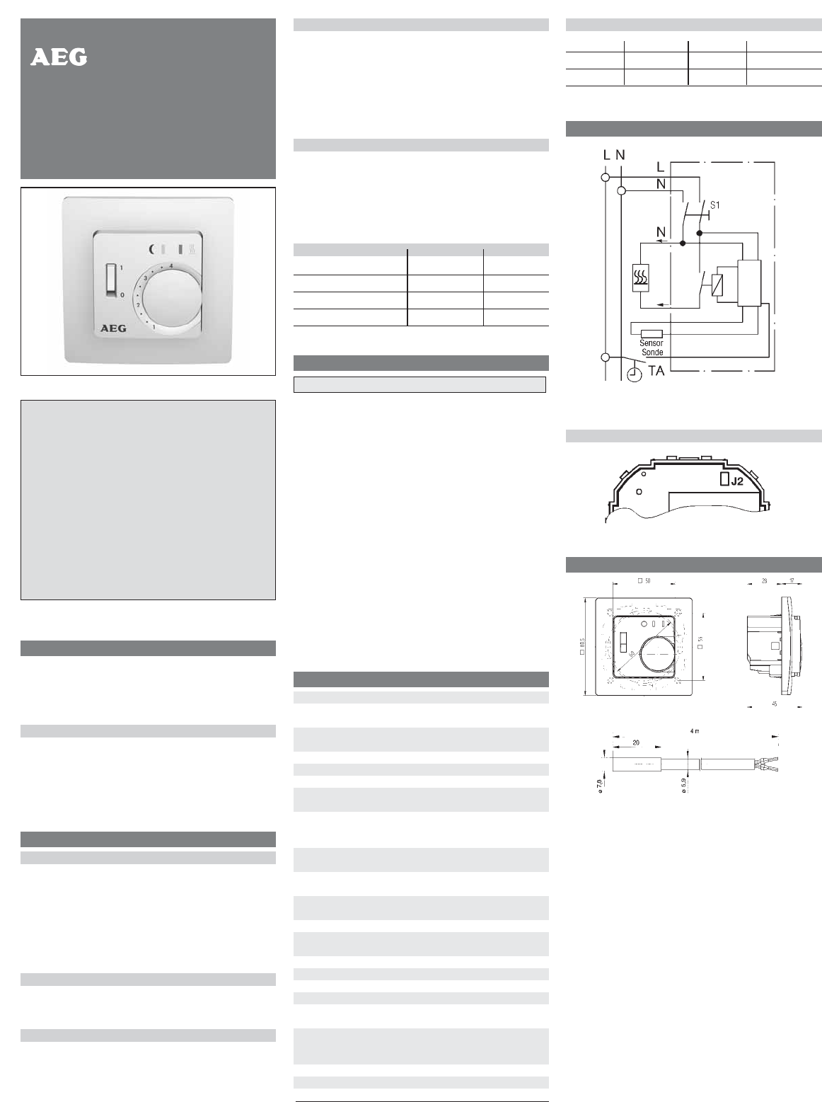
5. Circuit diagram
Caution: ਠ
Through-connector for earth (PE conductor)
Position of the jumpers
6. Dimensions
Errors possible-subject to alterations 280928/34615/2/0743