USER GUIDE
WS-1330
Thermometer with wireless outdoor sensors
COM
1
COM
2
WET
3
COM
%
RH
OVERVIEW
WET
COM
DRY
LO AL
HI
AL
LO AL
HI
AL
1
MAX
MIN
WET
COM
DRY
LO AL
HI
AL
LO AL
HI
AL
2
MAX
MIN
WET
COM
DRY
LO AL
HI
AL
LO AL
HI
AL
3
MAX
MIN
WET
COM
DRY
LO AL
HI
AL
LO AL
HI
AL
MAX
MIN
%
RH
1
2
3
4
5
6
7
8
9
10
11
12
13
14
15
16
17
18
19
20
21
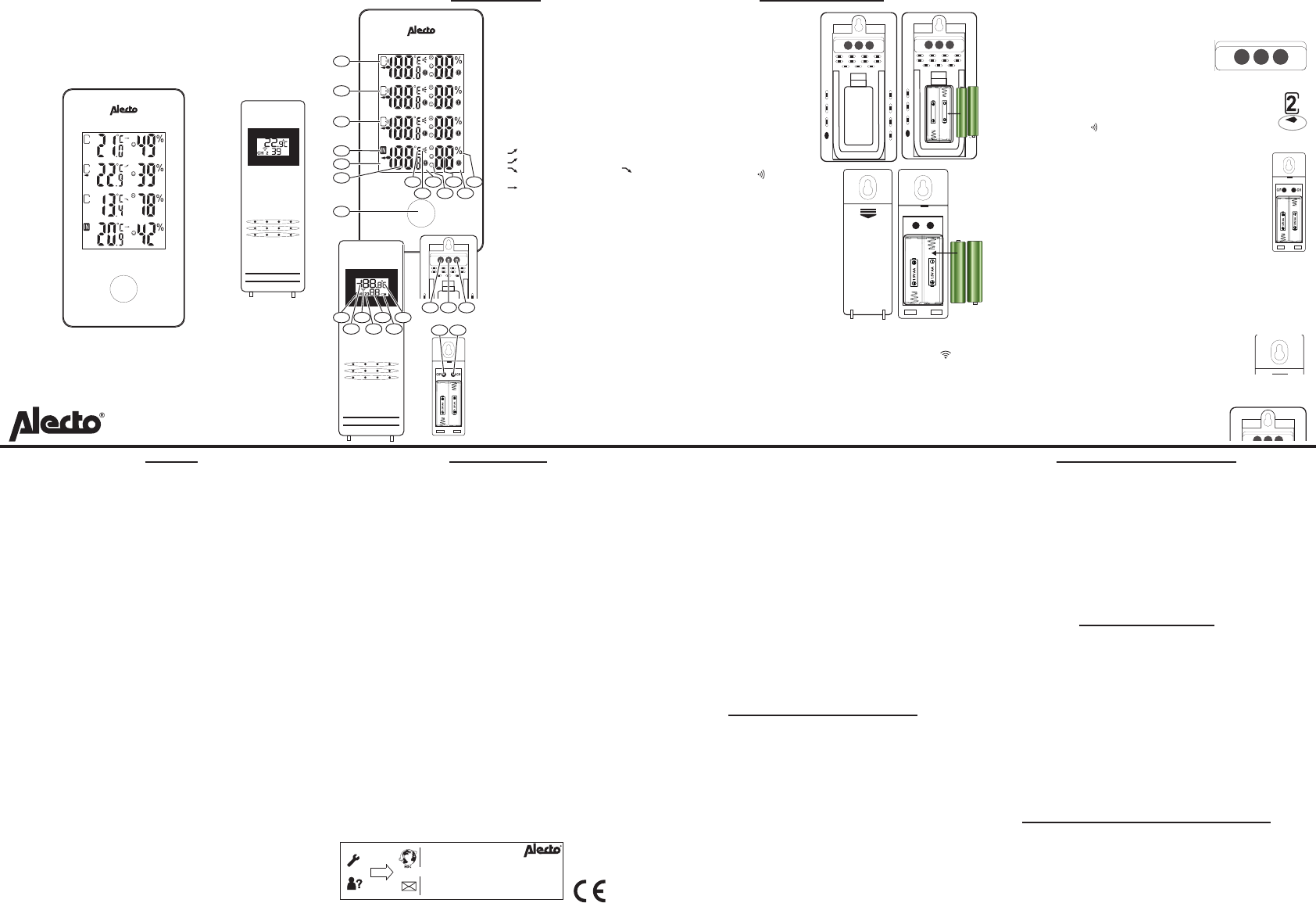
The display of this thermometer is divided
into 4 segments. These 4 segments are
nearly identical. 1, 2 and 3 are for the
outdoor sensors and IN is for the data of
the indoor unit. The functions of the indoor
unit are described below.
1. Function button
2. T
3. Minimum/maximum values indication
4. Indoor thermometer indication
5. Outdoor sensor 3 indication
6. Outdoor sensor 2 indication
7. Outdoor sensor 1 indication
8. Display in ºC or ºF
9. T
- next period 1ºC higher or equal:
- next period 1ºC lower or equal:
- lower by 1ºC in 1 hour: -
temperatuur variatie kleiner dan 1ºC:
)
10. High or low temperature alert indica-
tion
11. Humidity display emoticon (Com:
20-28ºC / 40-70%, W
tures / > 70%, Dry: all temperatures
/ <40%)
12. Humidity display
13. V
14. High or low humidity alert indication
15. Channel indication (CH)
16. T
17. T
18. Set transmission channel displa
19. Humidity display
20. Empty battery indication icon (in this
case, replace the batteries)
21. Display in ºC or ºF
22. “CH/+ ” button
23. “CF/- ” button
24. “ALERT ” button
25. “C/F ” button
26. “CH ” button
CH/+ CF/- ALERT
22 23 24
25 26
INSTALLATION
Indoor unit power supply:
1.
cover downward and pull the
cover o the
2.
1.5V
markings inside the battery
compartment. Batteries are
not included.
3. Replace the battery cover
As soon as the batteries are
installed, the outdoor unit
starts searching for any nearby
outdoor sensor for 3 minutes.
In the display the icon starts
ashing for each segment. P
instructions 4 through 6 within
3 minutes or refer to “manual
registration”.
4.
of the outdoor sensor downward
and remove it.
5.
1.5V-
ings inside the battery compart-
ment. Batteries are not included.
6. Set the outdoor sensor to the
desired transmission channel 1,
2 or 3 by pressing the “CH ” button. The display will show which
channel you’ve selected. -
ted to the outdoor unit (see transmission indication icon ) for
the registration. Use a unique channel for each outdoor sensor
7. C/F ” button to indicate the outdoor temperature in ºC
or ºF in the display of the outdoor sensor
8.
CH/+ CF/- ALERT
CH/+ CF/- ALERT
1.5V AAA
1.5V AAA
+ 1.5V AAA LR03 Alkaline -
- 1.5V AAA LR03 Alkaline +
AAA
+
- 1.5V AA LR6
AAA
+
+ 1.5V AA LR6
Manual registration:
Starting the registration of the outdoor sensor on the indoor unit
may be done manually
register the outdoor sensors.
The display of the indoor unit must be on
stand-by (no ashing icons).
1. Use the “CH/+ ” button to select the desired channel.
2. A dash underneath the channel number indicates which
channel is selected.
3. Now press and hold the “CH/+ ” button for 3 seconds until
the reception icon
starts ashing.
4. Open the battery compartment of the outdoor sensor and insert
the batteries if not already done so.
5. Press the “CH ” button of the outdoor sensor until the
desired channel is selected.
6. While selecting, the outdoor sensor transmits data to the
indoor unit.
7. The indoor unit now displays the value of the outdoor
sensor in the segment with the corresponding number
8. Use the “C/F ” button to have the outdoor temperature
shown in ºC or ºF in the display of the outdoor sensor
9. Replace the battery cov
The channel that hasn’t received any data is indicated by dashes.
The indoor temperature is always shown after inserting the batter-
ies.
Indoor unit and outdoor sensor placement:
The outdoor sensor may
from a wall b
wall, rst check whether -
door sensor and indoor unit
unit to properly receive the signal from the outdoor
sensor
Y
surface or you may use the suspension eyelet to
install the unit on a wall.
CH/+ CF/- ALERT
SETUP
Several functions on the indoor unit may be adjusted. The temper-
ture values can be displayed in ºC or ºF
set a maximum and minimum values alert. When the measurement
value is above or below this set v
alert function for both the temperature and the humidity
High and low alert setup:
The same procedure applies to each segment.
1. Use the “ CH/+ ” button to select the desired segment (1, 2, 3
or IN).
2. Press and hold the “ ALERT ” button for 3 seconds, the tempera-
ture and HI AL
3. Use the “+ ” and “- ” buttons to input the desired high tempera-
ture alert.
4. Press and hold the “ ALERT ” button for 3 seconds to activate the
alarm.
5. Press the “ ALERT ” button to continue to the low temperature
alert setup. The L
6. Use the “+ ” and “- ” buttons to input the desired low tempera-
ture alert and follow point 4 to activate.
7. Press the “ ALERT ” button to continue to the high humidity
value setup.
8. Use the “+ ” and “- ” buttons to input the desired high humidity
value alert and follow point 4 to activ
9. Press the “ ALERT ” button to continue to the low humidity
value setup.
10. Use the “+ ” and “- ” buttons to input the desired high humidity
value alert and follow point 4 to activ
11. Press the “ ALERT ” button to leave the setup menu.
12. Follow point 4 again to deactivate alarm points.
The above setup procedure applies to segments 1, 2, 3 and IN.
ºC or ºF display setup:
The indoor unit can display the temperature in ºC or ºF
T
1. Press and hold the “CF/- ” button for four seconds.
2. The display will switch between ºC and ºF
OPERATION
Maximum and minimum measured value:
Press the function button at the front. The selected segment shows
the maximum measured value with the “MAX” icon in the display
(temperature and humidity).
At this display press the function button again to display the min-
imum measured value. The “MIN” icon appears (temperature and
humidity).
Press the function button again to show the actual values (tempera-
ture and humidity).
or
1. CH/+ ” button to select the desired segment (1, 2, 3 or
IN).
2. CF/-” button to switch the display be-
tween the “MAX”
To delete the maximum and minimum measured values:
Y-
ment separately
1. CH/+ ” button to select the desired segment (1, 2, 3 or
IN).
2. CF/-” button to select the “MAX” value.
3. CF/- ” button to delete the maximum values
(temperature and humidity).
4. CF/-” button to select the “MIN” value.
5. CF/- ” button to delete the minimum values
(temperature and humidity).
The maximum and minimum values of the selected segment are now
deleted. T
please repeat the above for each segment (1, 2, 3 and IN).
Positioning tips:
• Never place the indoor unit in direct sunlight and keep it away
from heat radiating objects (lights, heaters, etc.)
• Never place the indoor unit next to large metal surfaces or heavy
electrical equipment, ensuring proper reception of the radio
controlled signals.
• The outdoor sensors not waterproof. Alw
on a spot protected against rain and wind.
• The distance between the indoor unit and outdoor sensor should
be no more than 50 meters. The transmission range can be
aected by nearby devices
• The range also depends on obstacles. Concrete walls between the
outdoor sensor and indoor unit will reduce the transmission range
more than plaster walls.
Rechargeable batteries:
Y
both the indoor unit and the outdoor sensor
batteries provide a lower voltage, reducing the lifespan and accu-
racy of the thermometer
using an external charger
BATTERY REPLACEMENT
Indoor unit:
After replacing the batteries of the indoor unit, all memories and
settings will be deleted.
Outdoor sensor:
After replacing the batteries of the outdoor sensor
re-register it to the indoor unit.
T
Note that the “CH ” button has the desired channel set.
RESET/SYSTEM ERROR
If the thermometer shows a possible error
the indoor unit and outdoor sensor
1. Remove the batteries from the indoor unit and outdoor sensor
2. Wait for at least 10 seconds and then replace the batteries.
3. Follow the registration procedure (see paragr
After several seconds the indoor unit and outdoor sensor will hav
recognized each other and you can start using the thermometer
again.
If you still have no connection or sound, please contact the customer
service of Alecto: www.alecto
SPECIFICATIONS
Indoor unit:
indoor temperature measurement range:
0°C ~ +50°C measuring time 30 sec.
measuring range humidity
Power supply: 2x 1.5V battery
Outdoor sensor:
measuring range temperature sensor:
-40°C ~ +70°C
measuring range humidity sensor: 20% ~ 95%
Power supply: 2x 1.5V battery
T 433.92 MHz
Maximum power: < 0 dBm
Range: up to 30 meters
DECLARATION OF CONFORMITY
This product is in accordance with the essential conditions and provi-
sions as stipulated in the European directive 2014/53/EU. This decla-
rat
Service
Help
Service Help
WWW.ALECT
SERVICE@ALECTO.NL
Hesdo, Australiëlaan 1
5232 BB, ‘s-Hertogenbosch
The Netherlands
WWW.ALECT
SERVICE@ALECTO.NL
Hesdo, Australiëlaan 1, 5232 BB,
‘s-Hertogenbosch,
The Netherlands
v3.0
V1.1