B. In Ch B
E. Out
D. Filters
F. On/Safety
C. Filters adjusting
A. Levels
A. Pre In
E. VSR D. Remote In
B. Speakers In
F. Power
C. Speakers Out
A. PLATES OPENING AND FIXING
D. CONNECTION CABLES
A. Pre In (preamplified inputs)
B. Speakers In (amplified input signals) - Red connections
C. Speakers Out
D. Remote In
E. VSR (Sub volume)
F. Power
A. Levels (0.2 ÷ 5 VRMS)
B. In Ch B Mode (In Ch B input configuration) - Light blue controls and inputs
C. Filters adjusting
D. Filters Mode (filters configuration) - Pink controls
E. Out Mode (outputs configuration)
F. On/Safety (switching on / protection)
C. VSR INSTALLATION (optional)B. FUSE REPLACEMENT
VCA.S.1
INTRODUZIONE
Il progetto SRx
La ringraziamo per aver preferito questo prodotto. Le sue ottime
prestazioni Le garantiranno una grande soddisfazione.
Legga questo manuale di servizio con particolare attenzione alle
precauzioni raccomandate per ottenere il massimo delle prestazioni
senza inconvenienti.
Precauzioni di sicurezza
•
L'impianto elettrico del veicolo
deve avere una tensione di
12VDC con negativo a massa. Verificare che il veicolo abbia
tali caratteristiche per evitare danni sia all'amplificatore che al
veicolo stesso.
•
Fissare adeguatamente l'amplificatore
con le viti in dotazione,
ponendo opportuna accuratezza se l'installazione è all'interno
dell'abitacolo. Inserire sistemi di fissaggio supplementari se
l'installazione è all'interno del vano motore. Il distaccamento
dal fissaggio durante la marcia del veicolo può causare grave
danno per le persone trasportate e per gli altri veicoli.
•
Il cavo di alimentazione
deve essere provvisto di isolamento
meccanicamente resistente ed autoestinguente alla fiamma.
La sezione deve essere confacente a quanto suggerito nel
presente manuale. Nel posizionamento, evitare la compressione
del cavo contro parti taglienti o nella vicinanza di organi
meccanici in movimento. Assicurarsi che sia adeguatamente
fissato per tutta la sua lunghezza. Interporre un serrafilo tra il
cavo positivo e negativo immediatamente a ridosso del morsetto
di alimentazione dell'amplificatore.
•
Applicare un portafusibile
vicino al morsetto positivo della batteria
e collegare su di esso il cavo di alimentazione dopo averne
collegata l'altra estremità all'amplificatore. Il valore del fusibile
deve essere uguale a quell posto all'interno dell'amplificatore.
Nel caso il cavo alimenti più amplificatori, il fusibile dovrà
avere un valore pari alla somma dei valori di tutti i fusibili presenti
sugli amplificatori.
•
Il volume di ascolto
deve essere di un livello tale da non coprire
i suoni provenienti dall'esterno del veicolo per la massima
sicurezza nella guida.
•
ATTENZIONE.
In condizioni particolarmente gravose la
temperatura dell'amplificatore può raggiungere i 90°C (194°F).
Accertarsi che la temperatura non sia pericolosa prima di
toccarlo a mani nude.
Precauzioni di funzionamento
•
Installare l'amplificatore
in zone del veicolo ove la temperatura
non scenda sotto gli 0°C (32°F) e non ecceda i 55°C (131°F).
•
La zona di installazione
deve avere un'adeguata circolazione
d'aria e non deve essere esposta ad umidità, pioggia, detriti
provenienti dall'esterno o dagli organi meccanici del veicolo.
Lasciare tra le estremità dell'amplificatore, corrispondenti
all'ingresso e all'uscita dell'aria, ed eventuali pareti almeno 5 cm (2”).
•
Le uscite di potenza
contrassegnate da -L e -R non debbono
essere collegate tra di loro. Nel caso si utilizzi un filtro crossover
stereo esterno, accertarsi che esso non abbia i negativi in comune.
•
Nell'installazione degli altoparlanti
e dei cavi che li collegano,
accertarsi che parti non isolate non vadano in contatto, anche
in modo saltuario, con il telaio del veicolo. In tal caso interverrà
la protezione dell'amplificatore.
•
La taratura del livello di ascolto
si effettua regolando il livello
dell'apparecchio pilota fino ai 3/4 del livello massimo;
successivamente, regolare i livelli dell'amplificatore fino ad
udire i primi fenomeni di distorsione.
Precauzioni di manutenzione ed affidabilità
•
Sottoporre a pulizia periodica l'amplificatore
evitando l'uso di
solventi aggressivi che potrebbero danneggiare le parti in
plastica o verniciate. Utilizzare un panno inumidito con acqua
e sapone, strizzarlo e pulire l'amplificatore. Ripassare con un
panno inumidito con sola acqua, infine passare un panno
asciutto.
•
Liberare da polvere e detriti solidi
le zone aperte dove si trovano
le manopole dei controlli frontali e le zone laterali alle due
estremità dell’amplificatore, in corrispondenza dell'aspirazione
e dell'uscita dell'aria. Questa operazione va effettuata
periodicamente aiutandosi con un piccolo giravite o un
pennellino. Evitare l'uso di aria compressa che spingerebbe i
detriti all'interno. Se necessario, rivolgersi ad un centro di
assistenza specializzato per la pulizia interna. Eventuali detriti
potrebbero ostruire e bloccare la ventola di raffreddamento;
ne conseguirebbe l'entrata in protezione termica anticipata
dell'amplificatore.
Il progetto SRx è quanto di meglio oggi possa essere disponibile
nel miglior compromesso tra compattezza, versatilità, prestazioni
in potenza, qualità del suono ed affidabilità.
Tutte le sue parti, come l'elettronica, le connessioni, le componenti
meccaniche, sono state realizzate attraverso il riesame di tanti
aspetti dell'amplificatore automotive cercando soluzioni innovative
tese a migliorare la producibilità e ad eliminare parti complesse
che, comunque, non avrebbero migliorato le prestazioni.
La circuitazione elettronica dello stadio finale ne è un esempio.
Normalmente amplificatori simili adottano la più semplice ed
economica circuitazione di tipo B, mentre l’SRx non rinuncia alla
superiore qualità della classe AB. Per ottenerla è stata sviluppata
una circuitazione altamente innovativa denominata DYNAB
(Dynamic AB) Class. Si tratta di una circuitazione per la polarizzazione
automatica della corrente di riposo che non necessita di complesse
tarature, a temperatura costante propria della classe AB tradizionale.
DYNAB unisce la semplicità della tradizionale classe B con le
caratteristiche qualitative degli amplificatori in classe AB.
Altro aspetto della particolarità del progetto SRx è dato dalle
connessioni. Si sono utilizzati dei morsetti non convenzionali per
il Car Audio ma largamente utilizzati nel settore elettrotecnico
professionale. Infatti sono del tipo a carrello mobile che non danneggia
il cavo e con il corpo in plastica autoestinguente alla fiamma, omologati
dai più importanti enti normativi di sicurezza internazionali.
Una menzione particolare va alle parti esterne in plastica. Anche
se a contatto con parti in alluminio la cui temperatura può
raggiungere i 90°C (194°F), non si hanno problemi in quanto si
tratta di un polimero con temperature di esercizio di 150°C (302°F)
e molto resistente agli urti, simile a quello dei paraurti delle auto
moderne.
Fattore imprescindibile del progetto SRx, però, è stato il
mantenimento di caratteristiche tecniche proprie di amplificatori
ritenuti di classe superiore.
Per lo stadio finale sono stati adottati dei generosi e lineari
transistors TO247 di ultima generazione. Ampia cura è stata
messa negli stadi di ingresso, sia Pre che Hi Level, adottando il
circuito LNS per l'eliminazione dei disturbi sempre presenti in
auto. Il crossover interno è stato particolarmente curato per la
massima versatilità permettendo un'ampia gamma di configurazioni.
L'alimentatore, di tipo non stabilizzato per ottenere la massima
efficienza, è stato dotato di bobina toroidale di livellamento secondario
per incrementare sia l'efficienza che l'affidabilità. La tensione di
batteria in entrata è stata filtrata con una bobina di modo comune
per l'abbattimento dei radiodisturbi ed il conseguente rispetto delle
recenti norme vigenti in auto (normativa europea 95/54/EC e
norma internazionale ECE10).
Le protezioni prevedono: temperatura massima, sovraccarico
in uscita, presenza DC (corrente continua) in uscita, RGP
(Resettable Ground Protection) per rilevare il cortocircuito tra le
uscite e la carrozzeria, fusibile di protezione generale all'interno
dell'apparecchio. L'intervento di una protezione si evidenzia con
l'accensione della spia rossa Safety. Eliminata la causa dell'entrata
in protezione, l'amplificatore riprende il normale funzionamento.
Su tutti gli SRx è possibile inserire il controllo remoto di volume
VSR (opzionale) specializzato per la sezione subwoofer.
è un amplificatore a 4 canali equipaggiato di filtri crossover escludibili
(Butterworth a 12 dB/ott.). Il sistema front dispone di filtro hi-pass ed il
rear di filtro hi-pass o lo-pass. Le frequenze di taglio possono essere
regolate tra 50 Hz e 220 Hz tramite potenziometri slider. Un selettore
per il funzionamento a 4-3-2 canali completa la dotazione di serie.
SRx 4
I
2. CONNESSIONI
3. FUNZIONI E CONTROLLI
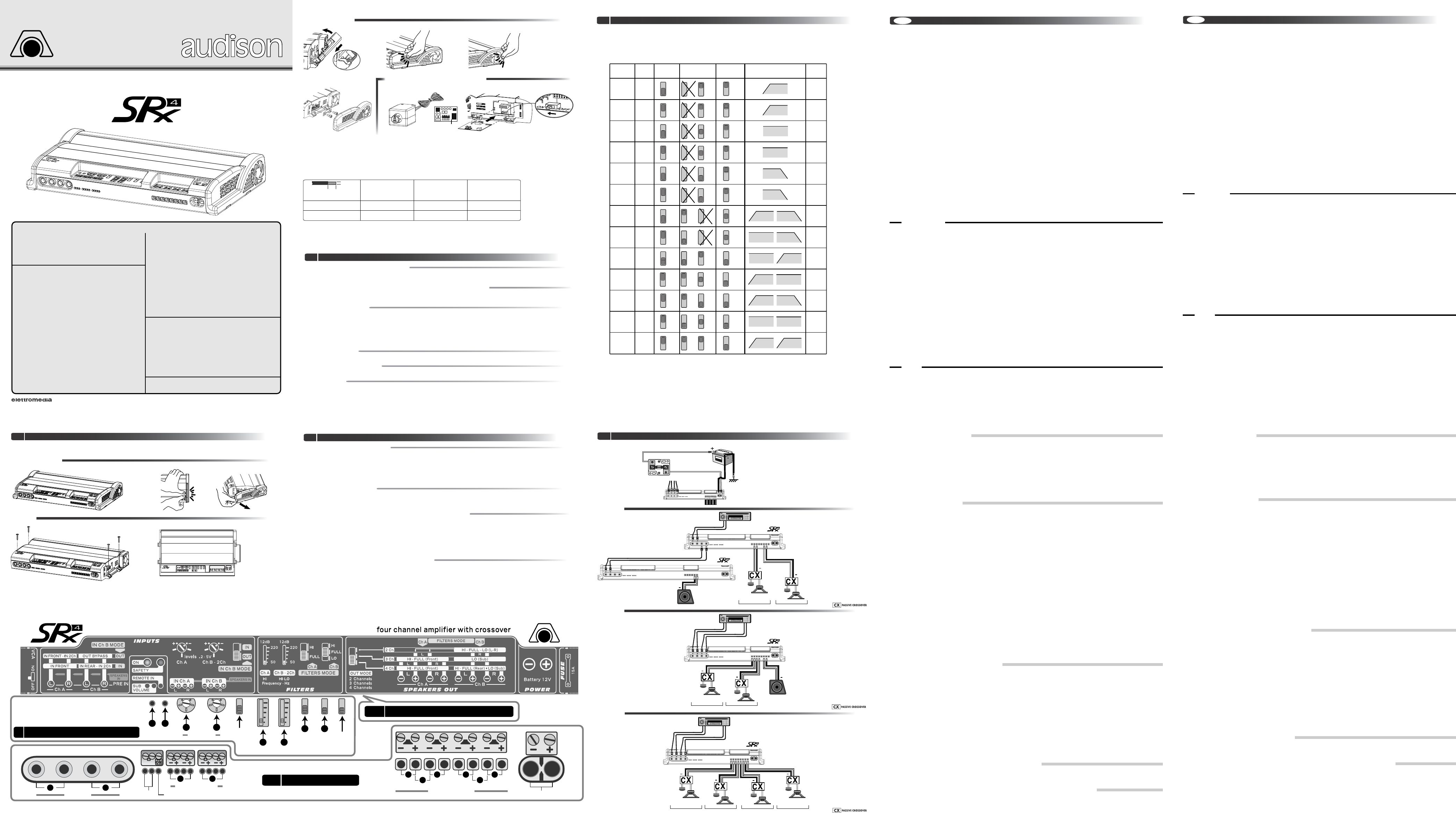
4. TABELLA DELLE CONFIGURAZIONI
A. Levels (0,2 ÷ 5 VRMS)
1 • Regola la sensibilità dei canali Ch A (Front).
Agisce sui canali sinistro e destro indicati (non operativo
nella configurazione 2 Ch).
2 • Regola la sensibilità dei canali Ch B (Rear); canale sinistro
e destro (2 Ch).
Agisce sui canali sinistro e destro indicati.
B. In Ch B Mode (configurazione dell’ingresso In Ch B)
Controlli e ingressi in azzurro
•
Configura la connessione Pre In Ch B: come ingressi IN REAR
o IN 2Ch (pos. IN); come uscite OUT BY-PASS (pos. OUT).
Nella posizione IN permette alla connessione Pre IN Ch B
di pilotare Ch B (4 Ch), il Subwoofer (3 Ch) o i canali sinistro
e destro (2 Ch). Nella posizione OUT i connettori Pre IN Ch B
sono uscite di segnale OUT BY-PASS per pilotare un
secondo amplificatore (con lo stesso segnale applicato a
Pre IN Ch A); in modalità 2 Ch l’ingresso attivo è Pre IN Ch A-
IN 2 Ch.
C. Filters adjusting
1 • Regola tra 50 Hz e 220 Hz la frequenza di taglio del filtro
HI-PASS Ch A (4 Ch, 3 Ch).
2 • Regola tra 50 Hz e 220 Hz la frequenza di taglio del filtro
HI / LO-PASS Ch B - 2 Ch (4 Ch, 2 Ch).
D. Filters Mode (configurazione dei filtri) - Controlli in rosa
1 • Configura i canali Ch A (Front): come HI-PASS o FULL RANGE
(4 Ch, 3 Ch).
2 •Configura i canali Ch B (Rear): come HI / LO-PASS o FULL
RANGE (4 Ch, 2 Ch).
E. Out Mode (configurazione delle uscite)
•
Configura l’amplificatore: 4 Ch (Front e Rear); 3 Ch (Front
e Sub); 2 Ch (Left e Right).
F. On / Safety (accensione / protezione)
1 •Led verde (ON).
Indica l'accensione dell'apparecchio.
2 • Led rosso (SAFETY).
Indica l'intervento delle protezioni.
1. INSTALLAZIONE
A. Apertura pannelli e fissaggio
1 • Smontaggio pannelli - Smontare il pannello sinistro (left) e destro
(right) facendo forza nei punti indicati.
2 • Fissaggio - Fissare l’apparecchio con le 4 viti in dotazione.
3 • Rimontaggio pannelli - Rimontare il pannello sinistro (left) e
destro (right) avendo cura che le linguette del pannello siano
inserite nella sede delle viti di fissaggio. Esercitare una forte
pressione nei punti indicati.
B. Sostituzione del fusibile
• Aprire il pannello destro (right) e sostituire il fusibile con quello
di ricambio fornito in dotazione.
C. Inserimento del VSR (opzionale)
•Aprire il pannello sinistro (left) e commutare lo switch VCA su ON.
Inserire il modulo VCA.S nelle apposite guide della placchetta e
quindi nel connettore.
D. Cavi di connessione
1 • Cavi d’alimentazione (per lunghezze di 4/5 m): con carichi di 4 Ohm
utilizzare audison cable POWERFLOW 9, con carichi di 2 Ohm
utilizzare audison cable POWERFLOW 7.
2 • Cavi per l’uscita altoparlanti.
3 • Cavi per gli ingressi di segnale a livello altoparlanti, per il remote
e l’accessorio VSR.
A. Pre In (ingressi preamplificati)
Il segnale da applicare deve avere un livello compreso tra
0,2 VRMS e 5 VRMS.
1 • Ingresso sinistro e destro: Ch A (IN FRONT); IN 2 Ch.
Ingresso che pilota solo i canali Ch A, i canali Ch A e Ch B
o i canali sinistro e destro (nella configurazione 2 Ch e selettore
IN Ch B MODE su OUT)
2 • Ingresso sinistro e destro: Ch B (IN REAR); IN 2 Ch.; uscite
OUT BY-PASS.
Selezionato come ingresso, pilota i canali Ch B o i canali
sinistro e destro nella configurazione 2 Ch, in alternativa a
IN FRONT. Selezionato come uscita è OUT BY-PASS del
segnale applicato a PRE IN Ch A.
B. Speakers In (segnali d’ingresso amplificati)
Connessioni in rosso
1 •Ingresso a livello altoparlanti sinistro e destro: IN Ch A
(Front); IN 2 Ch.
Non utilizzare se si usa la connessione preamplificata Pre In
IN FRONT.
2 •Ingresso a livello altoparlanti sinistro e destro: IN Ch B
(Rear); IN 2 Ch.
Non utilizzare se si usa la connessione preamplificata
Pre In IN REAR.
C. Speakers Out
1 • Uscita di potenza canale sinistro Ch A (Front): HI-FULL (4 Ch, 3 Ch).
Collegare al sistema di altoparlanti del canale sinistro anteriore
(modalità 4 Ch, 3 Ch).
2
•
Uscita di potenza canale destro Ch A (Front): HI-FULL (4 Ch, 3 Ch).
Collegare al sistema di altoparlanti del canale destro anteriore
(modalità 4 Ch, 3 Ch).
3
•
Uscita di potenza canale sinistro Ch B (Rear): HI-FULL-LO (4 Ch).
Collegare al sistema di altoparlanti del canale sinistro
posteriore (modalità 4 Ch).
4
•
Uscita di potenza canale destro Ch B (Rear): HI-FULL-LO (4 Ch).
Collegare al sistema di altoparlanti del canale destro
posteriore (modalità 4 Ch).
5
•
Uscita di potenza: canale sinistro HI-FULL-LO (2 Ch).
Collegare al sistema di altoparlanti del canale sinistro anteriore
(modalità 2 Ch).
6
•
Uscita di potenza: canale destro HI-FULL-LO (2 Ch); LO Sub (3 Ch).
Collegare al sistema di altoparlanti del canale destro anteriore
(modalità 2 Ch) o collegare all’altoparlante subwoofer
(modalità 3 Ch).
D. Remote In
•
Ingresso per l'accensione remota dell'amplificatore.
Collegare all'apposita uscita della sorgente.
E. VSR (Sub volume)
•
Ingressi per VSR (kit per il controllo a distanza del volume
del Sub, opzionale).
Da collegare al regolatore remoto di livello per subwoofer
VSR (kit opzionale). Il kit è composto dal regolatore VSR e
dal modulo VCA.S da installare nell’apposita sede.
F. Power
•
Morsetti per il collegamento dei cavi d’alimentazione
(battery: 12V).
Collegare il terminale + al morsetto positivo di batteria ed il
- allo chassis dell'autovettura. Tensione 12 VDC con negativo
a massa.
Tramite il selettore OUT MODE sono possibili tre configurazioni
principali: 4 Ch (Front e Rear) per pilotare un sistema Front e Rear
con uno o due ingressi; 3 Ch (Front e Sub) per pilotare un sistema
Front ed un subwoofer, con uno o due ingressi; 2 Ch per pilotare
un sistema stereo ad alta potenza o due subwoofer.
ATTENZIONE! Ad ulteriore protezione dell’impianto, si consiglia di
inserire un fusibile a lamina sul cavo che collega il polo positivo della
batteria al morsetto +BATT dell’amplificatore.
Questo fusibile andrà installato a circa 10 cm dalla batteria. Il suo
valore dovrà essere pari al doppio di quello del fusibile che equipaggia
l’amplificatore. Nel caso di impianti realizzati utilizzando più amplificatori
o amplificatori equipaggiati con più fusibili, esso dovrà essere pari al
doppio della somma dei valori dei vari fusibili.
5. COLLEGAMENTI ED ESEMPI DI CONFIGURAZIONI
INTRODUCTION
SRx project
Thanks for preferring this product. Its very good performances will
insure you utmost satisfaction.
Please read this owner’s manual paying special attention to our
recommendations in order to get the best performances without
problems.
Safety precautions
•
The vehicle electric system
must have 12VDC voltage with
negative to ground. Make sure your car has it in order to avoid
any damages to your amplifier and to the car itself.
•
Suitably fix the amplifier
with the screws given with it; pay
utmost attention if you install it into the driver’s compartment.
Use extra fixing systems if you install it inside the bonnet. If
the amplifier detaches itself while you are driving, it can severely
damage people and other vehicles.
•
Power supply cable
must have mechanically resistant and
self-extinguishing insulation. Its section has to comply with
what is indicated in this manual. When placing it, avoid to
press it against cutting parts or close to mechanical moving
objects. Make sure it is suitably fixed all along its length. Put a
clamping screw between positive and negative cable just
close to the amplifier power supply terminal block.
•
Put a fuse holder
close to the battery positive terminal;
connect one end of the power supply cable to it after
connecting its other end to the amplifier. The fuse value must
be the same as the amplifier built-in one. In case the cable
supplies several amplifiers, the fuse value will have to be
equal to the sum of the values of all other fuses in the system.
•
For safer driving,
we recommend to adjust volume not to
drown external traffic sounds.
•
WARNING.
When the amplifier works in particularly hard
conditions, it can reach 90°C (194°F). Make sure its
temperature is safe before touching it.
Functioning precautions
•I
nstall the amplifier
in locations where temperature is
between 0°C (32°F) and 55°C (131°F).
•
There must be suitable
air circulation where you install
the amplifier; this area must not be affected by humidity, rain,
external deposits or parts coming from the vehicle mechanical
devices. Let the amplifier ends (i.e. the parts where air goes in
and out) be at least 5 cm (2”) far from possible walls.
•
Don’t connect –L and –R power outputs one to the other.
If you
use an external stereo crossover, make sure that its negative
poles are not connected one to the other.
•
When installing speakers
and the cables that connect them,
make sure that non-insulated parts don’t touch the car chassis.
If they do, the amplifier protection intervenes.
•
Listening level calibration
is made by adjusting the source volume
up to 3/4 of its maximum level; then, adjust the amplifier levels
until you can hear distortions.
Maintenance and reliability precautions
•
Periodically clean the amplifier
avoiding to use aggressive
solvents that might damage plastic or painted parts. Dampen
a piece of cloth with water and soap, wring it and clean the
amplifier with it. Then, clean the amplifier by using a piece of
cloth dampened with water only; eventually clean it with a dry
piece of cloth.
•
Remove dust and solid deposits
from the open areas where
you can find front controls and from side areas at the amplifier
ends, where air should go in and out. This must be periodically
done by using a screw driver or a small brush.
Avoid to use compressed air since it would push the solid parts
into the amplifier. If necessary, please contact a specialised
after sale service centre for internal cleaning. Possible deposits
might obstruct or stop the cooling fan; the amplifier would then
go in safety.
SRx project is the best compromise between compactedness,
versatility, power performances, sound quality and reliability you
can nowadays find in the marketplace.
All its parts, like electronics, connections, mechanical components,
were realised by re-examining several aspects of automotive
amplifiers, looking for innovative solutions aiming at production
improvement and eliminating complex elements that, anyway,
wouldn’t have enhanced performances.
Final stage electronic circuitry proves it. Such amplifiers normally
use the simple and cheap B circuitry; SRx’s, on the contrary, don’t
give up AB class higher quality. In order to get it, we designed a
very innovative circuitry called DYNAB (Dynamic AB) Class. It is a
circuitry for automatic bias current adjustment; it is simple to
calibrate and it has constant temperature, typical of traditional AB
class. DYNAB combines B class easiness with AB class quality.
SRx connections are special, too. We chose terminal blocks that
are not normally employed in car stereo, rather commonly used in
professional electro-technical field.Approved by the most important
international safety norms institutions, they have screw clamp
connections (that don’t damage cable) and self-extinguishing body.
External plastic parts are special, too. Although they touch aluminium
parts that can reach 90°C (194°F), they don’t have any problems
since they are made of a special polymer that resists to 150°C
(302°F) and to crashes (similar to the material modern cars bumpers
are made of).
Our main goal when designing SRx was they had to have the
same technical features as so-deemed higher level amplifiers.
We employed the latest TO247 linear transistors for final stage.We
paid utmost attention to input stages, both Pre and Hi Level, using
LNS circuit for noise rejection. Built-in crossover is extremely
versatile and allows lots of configurations.
Power supply is not stabilised, in order to insure maximum efficiency;
it has secondary filtering toroidal coil to increase efficiency as well as
reliability. Input battery voltage was filtered through a common-mode
inductor, in order to decrease radio-disturbances and to comply
with the latest car norms (95/54/EC European Norms and ECE10
International Norms).
Protection circuits include: maximum temperature, output overload,
output DC, RGP (Resettable Ground Protection) to detect short
circuit between the output and the chassis, general protection fuse
inside the amplifier. When protection intervenes, Safety red
indicator is on. When the problem that made the amplifier go in
Safety is solved, the amplifier starts working again.
You can connect VSR, subwoofer volume remote control, to all
SRx amplifiers; it is optional.
It is a 4 channel amplifier with bypass built-in crossovers (12dB/Oct.,
Butterworth). Front system has a hi-pass filter; rear system has
hi-pass or lo-pass filter. Cut-off frequencies can be adjusted between
50 Hz and 220 Hz through slider potentiometers. This amplifier is
also provided with a switch for 4-3-2 channel functioning.
SRx 4
GB
2. CONNECTIONS
3. FUNCTIONS AND CONTROLS
4. CONFIGURATION TABLE
A. Levels (0.2 ÷ 5 VRMS)
1 • It adjusts Ch A (Front) channels sensitivity.
It acts on the indicated left and right channels (it does not work
in 2 Ch mode).
2 • It adjusts Ch B (Rear) and left and right channel (2 Ch)
sensitivity.
It acts on the indicated left and right channels.
B. IN Ch B Mode (IN Ch B input configuration)
Light blue controls and inputs
• It configures Ch B Pre In connection: as IN REAR or IN 2Ch
inputs (if set on IN), as OUT BY-PASS outputs (if set on
OUT).
When set on IN, it allows Ch B Pre In connection to drive
Ch B (4 Ch), subwoofer (3 Ch) or left and right channels (2 Ch).
When set on OUT, Ch B Pre In connectors are OUT BY-PASS
signal outputs to drive another amplifier (with the same signal
applied to Ch A Pre In); Ch A Pre In - IN 2 Ch input is activated in
2 Ch mode.
C. Filters adjusting
1 • It adjusts Ch A HI-PASS filter cut-off frequency between
50 Hz and 220 Hz (4 Ch, 3 Ch).
2 • It adjusts Ch B 2 Ch HI / LO-PASS filter cut-off frequency
between 50 Hz and 220 Hz (4 Ch, 2 Ch).
D. Filters Mode (filters configuration)
Pink controls
1 • It configures Ch A channels (Front) as HI-PASS or FULL RANGE
(4 Ch, 3 Ch).
2 • It configures Ch B channels (Rear) as HI / LO-PASS or FULL
RANGE (4 Ch, 2 Ch).
E. Out Mode (outputs configuration)
• It configures the amplifier as follows: 4 Ch (Front and Rear); 3 Ch
(Front and Sub); 2 Ch (Left and Right).
F. On / Safety (switching on / protection)
1 • Green led indicator (ON). It indicates the amplifier is on.
2 • Red led indicator (SAFETY). It indicates protection intervention.
1. INSTALLATION
A. Plates opening and fixing
1 • Plates removing - Remove left and right plates by pressing
where indicated.
2 • Fixing - Fix the device through the 4 screws given with it.
3 • Plates mounting - Mount left and right plates again minding to
insert their tongues into fixing screws housing. Strongly press
where indicated.
B. Fuse replacement
• Open the right plate and replace fuse with the spare one
given with the amplifier.
C. VSR Installation (optional)
•Open the left plate and put VCA switch on ON. Insert VCA.S module
into the proper slides on the plate and, then, into the connector.
D. Connection cables
1 • Power supply cables (4/5m long): with 4 Ohm loads, use audison
cable POWERFLOW 9; with 2 Ohm loads, use audison cable
POWERFLOW 7.
2 • Speakers output cables.
3 • Cables for speaker level signal inputs, for remote and VSR.
A. Pre IN (preamplified inputs)
Applied signal must be between 0.2 VRMS and 5 VRMS.
1 • Left and right input: Ch A (IN FRONT); IN 2 Ch.
Input that only drives Ch A channels, Ch A and Ch B channels or
left and right channels (in 2 Ch mode and with IN Ch B MODE
switch on OUT).
2 • Left and right input: Ch B (IN REAR); IN 2 Ch; OUT BY-PASS
outputs.
When it is selected as input, it drives Ch B channels or left and
right channels in 2 Ch mode, alternatively to IN FRONT. When it
is selected as output, it is the OUT BY-PASS of the signal applied
to Ch A PRE IN.
B. Speakers IN (amplified input signals)
Red connections
1 • Left and right speaker level input: IN Ch A (Front); IN 2 Ch.
Don’t use it if you employ IN FRONT Pre In preamplified connection.
2 • Left and right speaker level input: IN Ch B (Rear). IN 2 Ch.
Don’t use it if you employ IN REAR Pre In preamplified connection.
C. Speakers Out
1 • Ch A (Front) left channel power output: HI-FULL (4 Ch, 3 Ch).
Connect it to front left channel speakers system (4 Ch,3 Ch mode).
2 • Ch A (Front) right channel power output: HI-FULL (4 Ch, 3 Ch).
Connect it to front right channel speakers system(4 Ch, 3 Ch mode).
3 • Ch B (Rear) left channel power output: HI-FULL–LO (4 Ch).
Connect it to rear left channel speakers system (4 Ch mode).
4 • Ch B (Rear) right channel power output: HI-FULL–LO (4 Ch).
Connect it to rear right channel speakers system (4 Ch mode).
5 • Power output: HI-FULL–LO (2 Ch) left channel.
Connect it to front left channel speakers system (2 Ch mode).
6 • Power output: HI-FULL–LO (2 Ch) right channel; LO Sub (3 Ch).
Connect it to front right channel speakers system (2 Ch mode)
or to subwoofer (3 Ch mode).
D. Remote In
• Input for the amplifier remote switching on.
Connect it to the source proper output.
E. VSR (Sub volume)
• Inputs for VSR (optional kit for sub volume remote control).
Connect them to VSR, optional kit for subwoofer level remote
control. This kit consists of VSR control and VCA.S module, to
install into the proper housing.
F. Power
• Terminals for power supply cables connection (battery: 12V).
Connect + terminal to the battery positive and – to the car
chassis. Voltage is 12 VDC with negative to ground.
Three main configurations are possible through OUT MODE
switch: 4 Ch (Front and Rear) to drive a Front and Rear system
with one or two inputs; 3 Ch (Front and Sub) to drive a Front
system and a subwoofer with one or two inputs; 2 Ch to drive a
high power stereo system or two subwoofers.
WARNING! For extra protection, we recommend to put a strip fuse
along the cable that connects the battery positive pole to the amplifier
+BATT terminal.This fuse must be installed approx.10 cm far from the
battery. Its value will have to be the same as the amplifier built-in one.
When systems consist of several amplifiers or of amplifiers with several
built-in fuses, the value of this fuse will have to be equal to the sum of
the values of all other fuses in the system.
5. CONNECTIONS AND CONFIGURATIONS EXAMPLES
Owner’s Manual
Manuale d’uso
Mode d’emploi
Bedienungsanleitung
Manual de utilización
Manual do utilizador
U ivatelský Manuál
CAR POWER AMPLIFIER
AMPLIFICATORE DI
POTENZA PER AUTO
AMPLIFICATEUR DE PUISSANCE POUR AUTO
AUTO-HIFI-VERSTÄRKER
AMPLIFICADOR DE
POTENCIA PARA COCHE
AMPLIFICADOR P
ARA AUTOMÓVEL
AUTO ZESILOVAč