4
7
10
9
2 3
8
1 2 3
4
7
10
9
2 3
8
1 2 3
P
Diagrams and Lay
- Keep the warranty statement on hand to r
- Unless clearly permitted in the product documentation, do not use
accessories (such as cables) other than those included in the package
with this product.
• Switch (main unit)..................................................................................................... 1
• AC adapter................................................................................................................... 1
• Po
• Po
• Rubber feet.................................................................................................................. 4
• Serial number stickers............................................................................................. 2
• Quick Setup Guide (this document)................................................................... 2
•
• Limited lifetime warran
2018.05
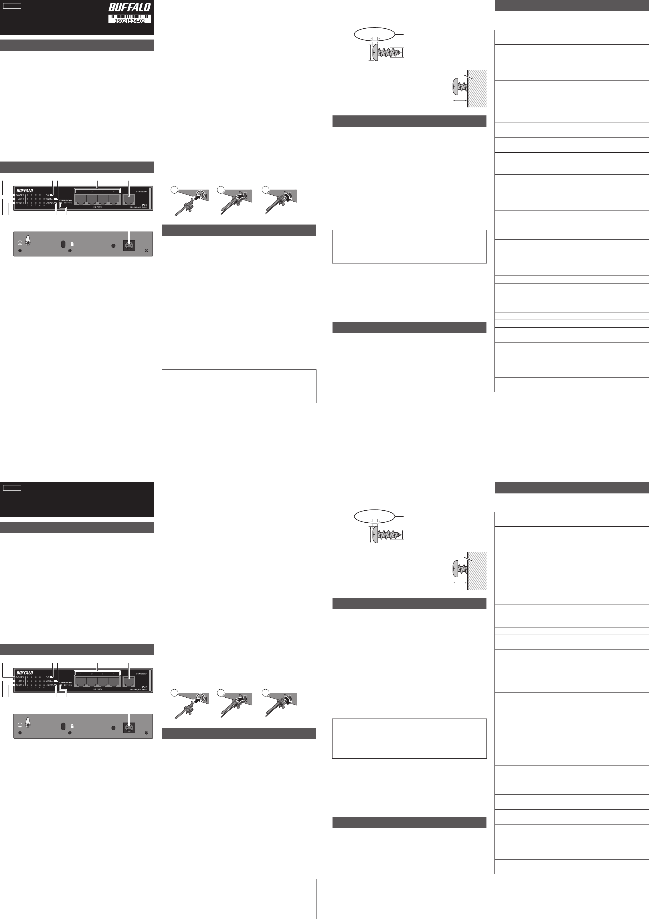
Quick Setup G
BS-GU2005P
1. PoE Limit LED
On (amber): PoE is supplying mor
devices. F
that draw more than 30 w
Blinking (amber): PoE power has been disabled t
because the maximum 50 watts of P
PoE po
number until the total P
Off
2. Loop LED
Blinking once per second (red): Loop blocked
Off
3. Po
On (green): P
Off
4. PoE LEDs
On (green): P
On (amber): Overcurrent, ex
Off
5. 1000 Mbps LEDs
On (green): 1000 Mbps link.
Blinking (green): Loop prev
Off
2 mm (0.08 in)
T
Loop Pr
This unit can detect and prevent network loops that can cause
interference in the network.
What Is a L
If both ends of an Ethernet cable are connected to the same hub
when multiple connections exist between two hubs, data may be sent
in a loop around the network, never getting to its destination and thus
wasting network capacity
interfere with other network communication.
Loop Pre
Off
On
is fixed. A
the blocked port will blink once per second.
T
Use the switch on the front of the swit
off
When a Loop Is Detected
Reconnect your Ethernet cabling, making sure that there ar
redundant connections.
Check Buffalo
the latest products or compatible models
T
If you are unable to connect to a network, check the following:
• Are the A
the power cable plugged into an outlet or sur
• Is the Ethernet cable connected correctly? Are any cables
disconnected or broken?
• Is the link/act LED on? If not, manually set the communication mode of
the connected hub or LAN adapter to 100M half-duplex or 10M
half-duplex.
* This unit automatically detects and adjusts for str
Ethernet cables, so either type of cable may be used.
** Site-terminated Ethernet cables are not recommended. A
pre-assembled cables.
*** This function automatically recogniz
Ethernet cable length and adjusts the operating power ac
Caution:
-
packet through the network every two seconds. If these packets disrupt
your network in any wa
- Loop prev
Installation
Precautions for Installa
• Do not install the device in an unstable location such as on an
unsteady table or an inclined surface.
• Do not place another hub or object that generates heat on top of this
unit.
• Please route all cables pr
them.
• Ensure the air vents on the pr
equipment or walls.
• Only use the AC adapter included with the pr
adapters may result in damage or fir
Floor or Shelf Mounting
Attach the supplied rubber feet t
use.
Mounting to a Metal Surface
T
Kit
W
T
the dimensions shown below
and slide the mounting holes into the base of the switch ov
-
at 3 mm (0.12 in) as shown on the right.
- Do NOT use the scr
product.
for wall mounting
Standards
IEEE 802.3ab (1000BASE-
IEEE 802.3 (10BASE-
Flow C
IEEE 802.3x (when operating at full duplex)
Back pressure (when opera
Ports
PoE ports: 4
Uplink ports: 1
All ports suppor
Compatible Cables
(*)(**)
1000BASE-
UTP/STP cables
100BASE-
cables
10BASE-
PoE: C
Connector RJ-45 8-pin connector (Shield type)
Po AC 100-240
Po Max.
External Dimensions
177 x 31 x 103 mm; 6.97 x 1.22 x 4.06 in
(excluding pr
W 0.5 kg (1.1 lb.)
Operating
Environment
Operating temperatur
0–50°C (32-122°F) with PoE supplying less than 30 w
0–45°C (32-113°F) with PoE supplying less than 50 w
Operating humidity: 10–85% (no condensation)
Acquir CE
T
1000 Mbps (1000BASE-
100 Mbps (100BASE-
10 Mbps (10BASE-
Switching Method Store and f
Jumbo Fr
9,198 bytes
(14 bytes header + 4 bytes FCS ar
T
Encoding Method
8B1Q4/4D-P
4B5B/ML
Manchester encoding (10BASE-
Access Method CSMA/CD
Data T
(
1,488,095 packets/second (1000BASE-
148,810 packets/second (100BASE-
14,881 packets/second (10BASE-
Switching F 10 Gbps
MAC Address T 2,048 (self-learning)
Buffer Memory 128 Kbytes
Aging T Approx. 300 sec
Other Functions
PoE
Loop prev
Po
Current C
Max. 1.2 A
When operating at 45°C (113°F) or abov
15.4 watts per port, 30 watts total
When operating at below 45°C (113°F):
15.4 watts per port, 50 watts total
Alternative A
T
Max. 100 m
φ6 mm (0.24 in) 3mm (0.12 in)
Use screws wher
(0.08 in) or less.
6. Link/Act LEDs
On (green): Link established.
Blinking (green):
Off
7. Loop prev
Switch loop prev
8. PoE ports
These Ethernet ports suppor
Ethernet power to these ports. Each port can supply up to 15.4 watts.
The maximum total supply for all 4 ports will vary according to the
operating temperatur
45°C (113°F) or above
Connect Ethernet devices to the switch in ascending or
number
to ports will be disabled in descending order by port number until
the total output power f
All ports suppor
duplex or half duplex) and transfer speed (1000, 100, or 10 Mbps) ar
selected automatically
9. Uplink port
Connect other hubs or switches to this port.
support PoE.
10. DC connector
Connect the included AC adapter to this c
adapter cable with the retaining band.
W
Max.3 mm
English
Caution:
- Do not put floppy discs, magnetic cards
near magnets. Doing so may delete or c
- If the switch is secured by the magnet kit alone, it should be no more than
75 cm (29.5 in) from the floor
Italiano
C
Diagrammi e la
-
- Salvo specificamente consentit
non usare accessori (come ca
di questo prodotto
• Switch
• Adattator
• Cavo di alimen
• F
• Piedini in go
• Adesivi numeri di serie............................................................................................ 2
• Guida rapida di installazione (questo documento)......................
• Garanzia........................................................................................................................ 1
• Garanzia a vita li
Guida rapida di installazione
BS-GU2005P
1. LED Limite P
Acceso (ambr
watt. P
dispositivi che assorbono più di 30 watt della P
Lampeggiante (ambra): alimentazione P
porte perché è stato superato il valor
L
decrescente rispett
valore in uscita totale è pari o inf
Spento: alimentazione P
disabilitata.
2. LED ricircolo
Lampeggiante una volta al sec
Spento: Lo swit
3. LED Alimentazione
Acceso (v
Spento: alimentazione assente
4. LED PoE
Acceso (v
Acceso (ambr
altri errori.
Spento: alimentazione P
5. LED 1.000 Mbps
Acceso (v
Lampeggiante (ver
Spento: 100 Mbps, collegamen
2 mm (0.08 in)
Specifiche tecniche
F
L
interferenze nella rete
Che cos’
Se entrambi i capi del cavo Ethernet sono collega
quando esistono connessioni multiple tra due hub
essere mandati in ricircolo sulla r
e comportando quindi una perdita di capacità della rete. Il passaggio
continuo di dati può interferire con altr
F
Spento
Acceso : se viene rilevato un ricir
a quanto il ricircolo non viene eliminat
collegamento/azione e 1000 Mbps (se attiv
bloccata lampeggeranno una volta al sec
Attivar
Usare lo switch ant
antiricircolo
Quando viene rilevato un ricir
Ricollegare i cavi Ethernet, assicurandosi che non ci siano connessioni
ridondanti.
V
sui prodotti più recen
Risoluzione problemi
Se non è possibile collegarsi alla rete
• L
correttamente? Inoltre
presa o ad un elemento di pr
• Il cavo Ethernet è collegato c
rotti?
• Il LED collegamento/azione è acceso? Se non lo è, impostar
manualmente la modalità di comunicazione dell’hub collegato o
dell’adattator
* L
incrociati, quindi è possibile usare qualsiasi tipo di ca
** Cavi Ethernet interr
*** Questa funzione riconosce automaticamente lo sta
della porta e la lunghezza del cavo Ethernet e adatta l’alimentazione di
conseguenza.
Attenzione:
- Quando la funzionalità antiricircolo è abilitata, lo switch in
pacchetto di rilevamento ricirc
pacchetti interferiscono in qualche mondo con la rete
funzionalità antiricircolo
- La funzionalità antiricircolo non può rilevare o bloc
Installazione
Precauzioni per l’
• Non installare il dispositivo in una sede non stabile come ad esempio
un tavolo instabile o una superficie inclinata.
• Non posizionare un altro hub od oggetto che gener
questa unità.
• Posizionar
inciampino.
• Assicurarsi che gli sfiati di aerazione del pr
da altri dispositivi o da muri.
• Usare solo l’
adattatori CA può comportare danni o causare incendi.
Installazione a pavimento o su scaffale
Prima dell’uso attaccare i piedini in gomma inclusi negli angoli inf
dell’unità.
Installazione su una super
Per installar
“BS-MGK-A Magnet Kit”
pz).
Installazione a parete
Per installar
delle dimensioni indicate di seguito
e far scorrere i f
- La testa della vite deve spor
come mostrato a destra.
- NON usare le viti incluse con il prodott
incluse con il prodotto non possono esser
per l’
Standard
IEEE 802.3ab (1000BASE-
IEEE 802.3 (10BASE-
Controllo flusso
IEEE 802.3x (per funzionamento full duplex)
Pressione post
Por
Porte P
Porte Uplink: 1
T
Cavi compatibili
(*)(**)
1000BASE-
5 o superiore
100BASE-
superiore
10BASE-
PoE: ca
Connettore Connettore a 8 pin RJ-45 (tipo schermo)
Alimentazione AC 100-240
Consumo energetico Max.
Dimensioni esterne
177 x 31 x 103 mm; 6.97 x 1.22 x 4.06 in
(escluse parti sporgenti)
Peso 0.5 kg (1.1 lb
Ambiente operativ
T
0–50°C (32-122°F) con alimentazione P
0–45°C (32-113°F) con alimentazione P
Umidità di esercizio: 10–85% (senza condensa)
Standard acquisiti CE
V
trasmissione
1000 Mbps (1000BASE-
100 Mbps (100BASE-
10 Mbps (10BASE-
Metodo di accensione
Archivia e inoltra
Fr
9,198 bytes
(intestazione 14 byte + 4 b
Metodo di codifica
trasmissione
8B1Q4/4D-P
4B5B/ML
Codice Manchester (10BASE-
Metodo di accesso CSMA/CD
V
trasferimento da
(velocità effettiva)
1.488.095 pacchetti/secondo (1000BASE-
148.810 pacchetti/secondo (100BASE-
14.881 pacchetti/secondo (10BASE-
Infrastruttura di scambio
10 Gbps
T
2.048 (apprendimento automa
Memoria buffer 128 Kbytes
Periodo di aging Circa 300 secondi
Altre funzioni
PoE
F
Risparmio energetico (***)
Consumo di corrent
Max. 1,2 A
Se in funzione a una temperatura di 45°C (113°F) o superiore:
15,4 watt per porta, 30 watt totali
Se in funzione a una temperatura di 45°C (113°F):
15,4 watt per porta, 50 watt totali
Alternativa A
Distanza di trasmissione
Max. 100 m
φ6 mm (0.24 in) 3mm (0.12 in)
Usare le viti in cui questa sezione è di 2
mm o meno.
6. LED Collegamenti/Azioni
Acceso (v
Lampeggiante (ver
non attiva.
Spento: collegamento non stabilit
7. Loop prev
Attivare e disa
8. Porte P
Queste porte Ethernet suppor
necessitano di alimentazione Ethernet a queste porte. Ogni porta
può fornire fino a 15,4 watt
per tutte le 4 porte varierà in base alla temperatura di esercizio
inferiore a 45°C (113°F) , 50 watt
Collegare i dispositivi Ethernet allo switch in or
rispetto al numero delle porte. Se l’alimentazione complessiva
massima per il PoE super
disabilitata in ordine decresc
a quando l’alimentazione totale in uscita per il P
inferiore a 50 watt
T
ottimale (full duplex o half duplex) e la velocità di trasf
(1.000, 100 o 10 Mbps) sono selezionate automaticament
9. Porta Uplink
Collegare altri hub o interrutt
supporta il PoE.
10. Connettor
Collegare a questo c
cavo dell’
Par
Max.3 mm
Attenzione:
- Non mettere floppy disc
archiviazione magnetici vicino alle calamite
potrebbe eliminare o danneggiar
- Se lo switch è vincolato solo dal kit magnetico
a più di 75 cm dal suolo.