• Second, the -12V ground terminal must be connected.The -12V ground is the
second slot(B) from the left of the powerconnector.This cable has to be faste-
ned securely to the chassis of the vehicle with the same gauge cable as the posi-
tive cable (the same amount of power has to run through it). Preferrably you
should have the same ground connection for your entire system. Ensure that all
paint, undercoating or any other insulation is removed from the area where you
want to make your ground connection to.
• Third to connect is your remote turn-on.The R (remote turn on) is the third
slot(C) from the left of the powerconnector. Many radio-cassette and CD-players
have an output terminal for connection of the Remote turn on. If you don’t have
such an output, a separate switch must be installed to control your remote
on/off functions.
• The last terminal to connect is your Delayed Remote output.The D/R (Delayed
Remote output is the first slot (D) from the right of your powerconnector.The
delayed remote output should be connected to all the amplifiers and other
equipment following the CX4R, so they can be started with a 2 seconds delay.
Signal input
The next to connect is your signal input. Choose the correct length and style of
RCA patch cables for your needs. Better RCA’s, such as the ones from the
Caliber CL 600 and CL 800 Get Connected Series, have gold-plated connectors
and multiple layers of shielding for better noise rejection.These twisted cables
give a better result in combination with the balanced outputs. (Consult your offi-
cial Caliber dealer about these cables and RCA’s).
Be extra careful when running your RCA patch cables. Car environments are
notorious for poorly insulated wires.This means that hiss, engine noise and fan
noise can easily be picked up trough RCA cables, if ran incorrectly. As a precau-
tion, avoid placing your RCA’s near large wire looms and electronic fans when-
ever possible.
Connect the patch cables to the RCA output of your source unit. Run the RCA
cables to the location of the CX4R, and connect them to the input RCA con-
nectors of the CX4R. Be sure to connect the right channel to the right channel,
and the left to the left. (In an audio system the right always has red RCA con-
nectors, and the left RCA connectors are white or black).
Signal output
Once you have connected the inputs, it is time to connect the outputs. Be care-
ful to connect, via RCA patch cables, the correct output to the correct amplifier.
Ta ke good care in the balance of your signal (Right to right, and left to left).
Now that you have connected all your signal and power cables, it is time to con-
nect your battery again, and place the 1A fuse in the fuseholder.
5
SIGNAL INPUT / OUTPUT
4
MOUNTING AND CONNECTING YOUR CX4R
15-20 Modulair Resistor Units
These 16-pins modulair resistor units are what it is all about with the CX4R.
They allow you to create a really personal sound, which is especially tuned
for your installation. By changing the resistor value of these units, you can
determine your own crossoverfrequency per channel.The sequence of these
resistor units is shown in the graphics below them. So, module 1 (15) is for
the High Pass side of your Band Pass channel, and module 2 (16) is for the
Low Pass side of your Band Pass Channel, and so on.
By giving all the modules your own resistor value (and thus their own bandwidth)
you can tune your installation to perfection. How you can calculate the resistor
values for each frequency is demonstrated in a separate chapter.
21 Clipping LED’s
These clipping LED’s will warn you when an output is clipping.When they lit
up continously the output is clipping, and you should immediatly adjust the
outputlevel, or you will damage your speakers.When these LED’s start to
flicker, the output is almost clipping.This is a warning sign for you to take
extra care to the output level.
22 Outputs
Docking ports for the RCA cables which lead to the various amplifiers.
Mounting your CX4R
Find a steady, secure area to mount your CX4R. Be sure it is accessible, but not in an
area where the adjustments may be bumped by accident. Use the chassis of the
CX4R as a template and mark the locations of the mounting holes.Predrill the moun-
ting holes using a 2,5 mm diameter drill bit and use the screws supplied with your
CX4R to fasten your 4-way crossover. Make sure the screws are tightened securely.
Getting your power started
REMEMBER TO ALWAYS DISCONNECT BATTERY GROUND
BEFORE WORKING ON A VEHICLE’S ELECTRICAL SYSTEM
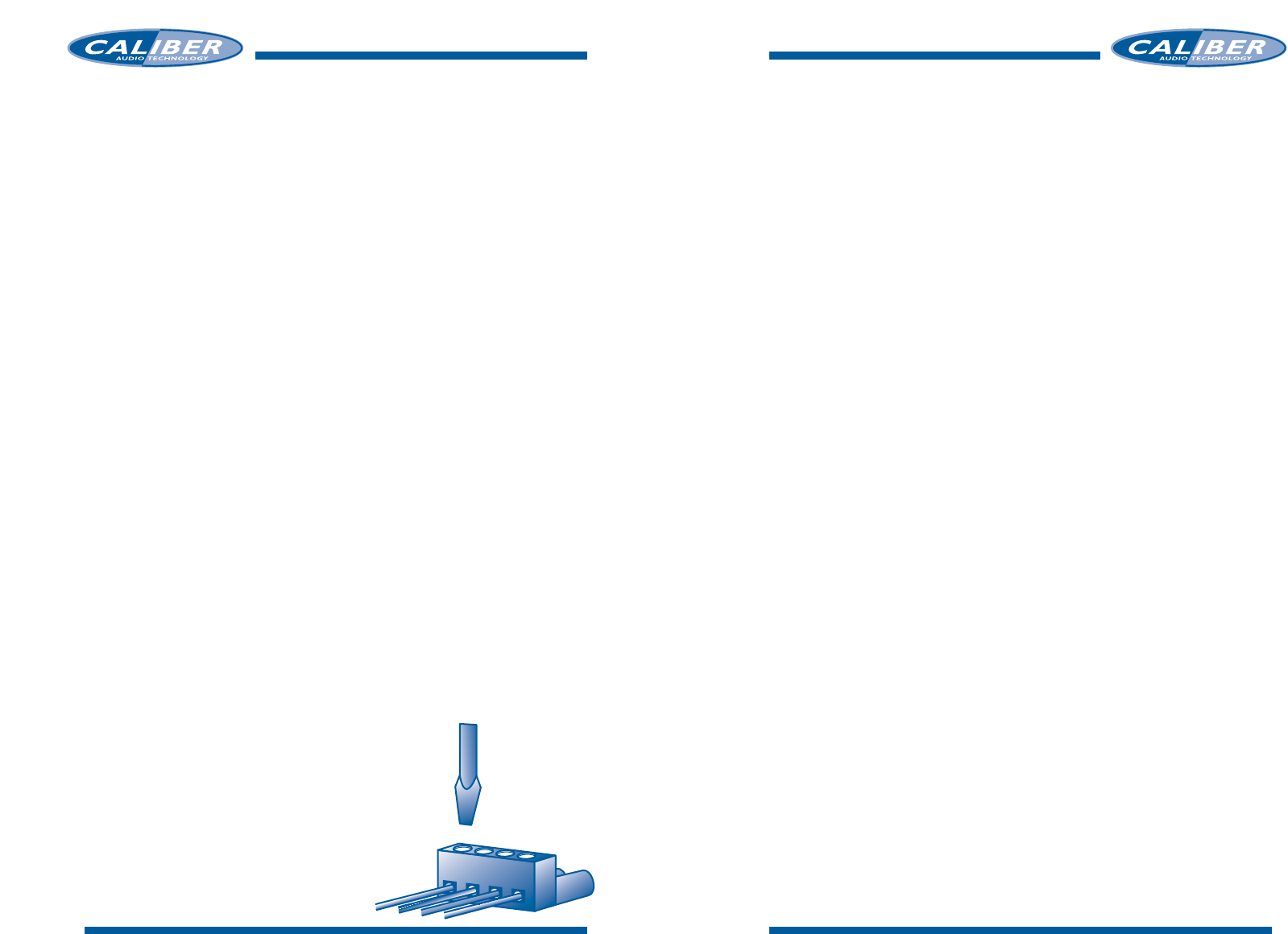
• First, the +12V terminal is connected.The +12V termi-
nal is the first slot(A) from the left of the powercon-
nector. Use the same +12V source as you are using for
your amplifiers, in order to avoid picking up noise due
to voltage differences.
Don’t forget to add an inline fuseholder holding a
1A fuse at the beginning of the powercable for the
CXQ20.This to protect both your vehicle and
audiosystem in case of a short.