L
A
B
AT
B
AT
A
sensor
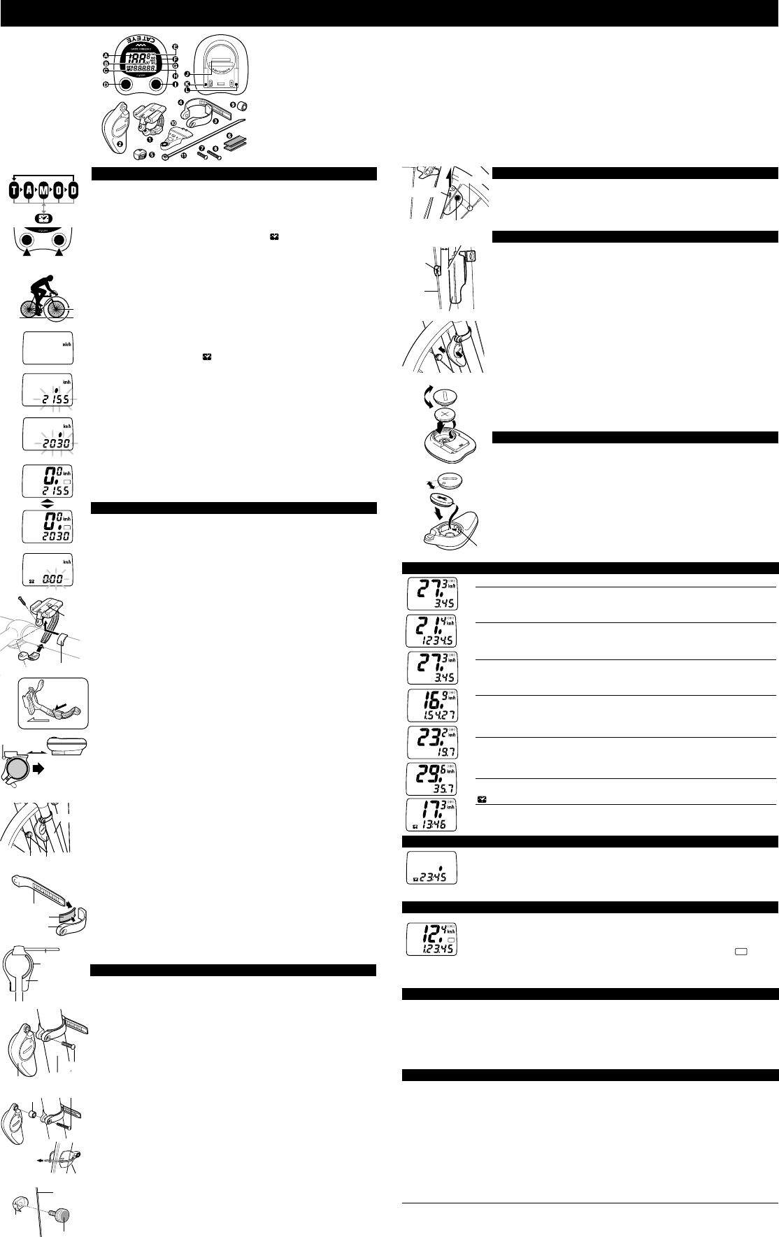
OPERATION FEATURES
Two buttons are provided on the top of the main unit and two on the bottom.
These buttons are used as follows:
•Mode Button (top left button)
Whenever this button is pressed, the mode display changes in the order
shown in fig.1, and the data is displayed on the sub-display. Note: If this
button is kept pressed for more than 2 seconds,
display appears.
•Start/Stop Button (top right button)
Measurement of trip distance, elapsed time and average speed is started or
stopped when the start/stop button is pressed. Whenever this button is
pressed, start and stop are repeated. During measurement the speed scale
symbol blinks.
Note: This button does not function if the auto mode function is set to ON
[Refer to the explanation of the Auto (Automatic Start/Stop) Function below].
•Set Button (bottom left button)
• To set the wheel circumference:
Stop the measurement in the (O) mode, then press the SET button.
• To set the 24-hour clock time:
Stop the measurement in ( ) mode, then press the SET button.
• To set auto mode to ON or OFF:
Select the (T),(A) or (D) mode, then press the SET button.
•AC (All Clear) Button (bottom right button)
When this button is pressed, all the data stored in memory is cleared.
After all displays illuminate, the "mile/h" symbol illuminates. This button should
be pressed only after replacing the battery or when irregular display of infor-
mation occurs due to static electricity,etc. Once this button is pressed and all
memory is erased, it will be necessary to set the wheel circumference, time,
etc. again. (refer to Main Unit Preparation)
Reset Operation: (Fig.2)
Press left button to select any mode except total distance (O) and press left
and right buttons together. Stored data of trip distance (D), elapsed time (T),
average speed (A) and maximum speed (M) are all reset to zero. (In the total
distance display mode, the current wheel circumference (A) or (B) is shown.)
MAIN UNIT PREPARATION
User must make the following setting according to instructions before
the cyclocomputer can be used properly.
1. How to measure the exact Wheel Circumference (L)(Fig.3)
First, adjust tire pressure and then put a mark on the tire tread and the ground
simultaneously. Then ride the bike one full wheel revolution. Mark the ground
at the end of one revolution and then measure the distance between the two
marks. This measure is your actual wheel circumference. Or, the "Setting Val-
ues Cross Reference Table" can help you to find out an approximate wheel
circumference according to tire size.
2. Setting the Speed Scale (Fig.4)
When the AC button is pressed and all displays illuminate then the "mile/h"
appears as shown in fig.4. "km/h" and "mile/h" are displayed alternatively each
time the right button is pressed. Select any speed scale as desired and press
SET button to complete the setting.
3. Setting the Wheel Circumference (Fig.5.6)
This cyclocomputer is able to memorize two different wheel circumferences.
One main unit can be used on two bicycles subject to buy another set of
bracket and sensor.
Two wheel circumferences, (A) 2155mm and (B) 2030mm, have been set be-
fore the cyclocomputer left our factory. The (A) wheel circumference 2155mm
(standard for 27 inch tire) will blink as shown in fig.5. If you want to enter
2155mm and 2030mm, simply press the SET button. If you want to change,
press either the right button to increase or left button to decrease the number.
To change the number rapidly keep the button pressed. Once you reach the
setting you want, press the SET button. If you want to set a second circumfer-
ence, press the left and right buttons together before pressing the SET button.
The wheel circumference 2030mm is displayed and blinks(fig.6). Set to a de-
sired wheel circumference in the same manner as the first circumference set-
ting and press SET button to complete the setting.
4. Selecting one of the two Wheel Circumference (Fig.7)
Set the Auto Mode to ON. (Refer to the explanation of Auto Mode function.)
While keeping the right button pressed , press the SET button. The first wheel
circumference measurement will be displayed for a few seconds, then the sec-
ond setting will appear.
5. How to reset the Wheel Circumference
Select the (O) mode and stop the measurement. Press SET button and the
already set wheel circumference will blink on the sub-display. Refer to '3.Set-
ting the wheel circumference' to complete the setting.
Setting the 24-hour Clock (Fig.8)
Press left button for more than 2 seconds to select the 24-hour clock display.
Stop the measurement by pressing the right button. Press SET button and the
minute display will start to blink. Press right button to select a minute time
ahead of the current time by 1 to 2 minutes. Next press left button and the hour
will blink. Press right button to set to current hour time. Press SET button to
complete the setting.
MOUNTING TO BIKE
Attach the bracket near handlebar stem, using rubber pad (fig. 9). Cut and
adjust the length of the rubber pad if necessary.
• Slide the main unit onto the bracket from front until it clicks into position. To
remove the main unit, pull it forward while depressing the lever on bracket
(fig.10).
How to Mount the Sensor on the Right Front Fork Leg.(fig.11)
Mount the sensor in the highest possible position on the right front fork leg.
Adjust the position, clearance and direction as follows:
(1) Insert the band B into the slit of the band A, and put the rubber pad inside
of the band A (fig. 12). Adjust the length of the bands in order that the
screw-fastening part of the bands is parallel when mounted to the fork (fig.
13). * To pull out the band B from band A, tug strongly.
(2) Mount the adjusted bands to fork along with the sensor, by temporarily
tightening the screw (fig. 14).If the space between front fork and spoke of
your bike is big, use the spacer and long screw as in the fig.15, so that the
clearance between sensor and magnet will be approx. 5mm.
(3) Attach the magnet securely to the right side of the spoke (fig. 16) so that
the magnet properly faces the sensor zone (fig. 17).
(4) A 5mm clearance shall be kept between the sensor and magnet(fig.18).
Then align the magnet with sensor zone (fig.16). Meanwhile, the sensor
shall aim at the main unit indicated by the triangle marked on the sensor.
Then tighten the screw to secure the sensor in position. Cut the excess
sensor band B with scissors or the like.
Check points for sensor mounting:
1.
2.
3.
INSTRUCTION MANUAL
E
bracket
slide
front
front fork
magnet
sensor band B
sensor band B
front fork
screw
magnet
CLOSE
CR2032
OPEN
CR2032
sensor
rubber pad
sensor
rubber pad
Fig.9
Fig.10
Fig.11
Fig.12
sensor band A
Fig.14
Fig.15
Fig.18
Fig.19
CLOSE
OPEN
Fig.20
sensor zone
spoke
rubber pad
sensor band A
Fig.13
parallel
lever
Reset
less than
5mm
A
POWER SAVING FUNCTION
When the main unit is left without receiving any signal for one hour, the power will
be turned off automatically. Resulting in SLEEP state in which only the 24-hour
clock displays. The main unit can not receive any signal in this state. Press left or
right button to restore signal reception.
Note: Remember to restore signal reception before every journey.
MAINTENANCE/PRECAUTIONS
• Do not leave the main unit exposed to direct sunlight when the unit is not in use. Do not disassemble
the main unit.
• Don't pay too much attention to your computer's functions while riding! Keep your eyes on the road
and give due consideration to traffic safety.
• Check the relative position of magnet and sensor periodically.
• For cleaning, use neutral detergent on soft cloth, and wipe off later with dry cloth. Do not apply paint
thinner, benzine, or alcohol, which may damage on the surface.
TROUBLE SHOOTING
No display. ------------------------------------------------------ Replace the main unit battery with new one.
Incorrect data appears. -------------------------------------- Execute "All Clear" operation.
Figures do not appear on the main display ------------- Cancel the power saving function.
Current speed does not appear. --------------------------- Check the sensor position and direction.
Speed is not displayed when riding with high speed or at low temperature.
--------------------------------------------------------------------- Check the sensor position and direction.
--------------------------------------------------------------------- Has the battery worn out?
Even when the right button is pressed, the cyclocomputer does not operate.
--------------------------------------------------------------------- Set the auto mode to OFF.
The entire liquid crystal screen is dark and unusual display is seen where it should not be.
--------------------------------------------------------------------- It returns to normal state if left in the shade.
Display response is slow. ----------------------------------- It returns to normal state when temperature rises.
SPECIFICATIONS
Applicable Cycle Sizes 10 mm - 2,999 mm(Initial value: A:2155 mm B:2030 mm)
Power Supply Main unit: ------------------------------------
Sensor with transmitter: ------------------ Lithium Battery (CR2032)x1/approx. 1,000miles
Dimension / Weight 2"x 1-13/10"x 29/32" / 1.2 oz (29 g)
* The specifications and design are subject to change without notice.
T
AT
A
AUTO (AUTOMATIC START/STOP) FUNCTION
The Cordless 2 is equipped with a selective auto function allowing automatic start
or stop of measurement without using the right button.
How to Set On/Off the Auto Function
Select (T), (D) or (A) to sub-display and then press SET button. The
AT
symbol
will display when auto function is set ON. Repeat to set OFF the auto function.
Note: In SLEEP state, auto start will not function. Press left or right button to restore
signal reception first. (Refer to Power Saving Function)
S Current Speed 0.0(3.0) to 65.9 miles/hr ±0.3mile/h
This is always displayed on the main display and updated once a second.
O Total Distance 0.0 to 99,999 miles ± 0.1mile
This is continuously measured until battery wears down or all clear operation is
done. At 100,000 miles(km), it returns to zero and counting begins anew.
D Trip Distance 0.00 to 999.99 miles 0.01mile
The trip distance from start to current point is displayed. With Reset operation, it
returns to zero.
T Elapsed Time 0:00'00" to 9:59'59" ± 0.003%
Elapsed time is measured from start to current point, in units of hours, minutes and
seconds. At 10 hours, it returns to zero and counting begins anew. With Reset
operation, it returns to zero.
A Average Speed 0.0 to 65.9 miles/hr ± 0.3mile/h
The average speed from start to current point is displayed within 27 hours 46 min-
utes 39 seconds (99,999 seconds) or 999.99 miles (km). If either is exceeded, (.E)
is displayed and calculation ceases.
M Maximum Speed 0.0 (3.0) to 65.9 miles/hr ±0.3mile/h
With Reset operation, it returns to zero and counting begins anew.
24 hr. Clock Time 0:00´ to 23:59´ ± 0.003%
The current time is displayed by a 24-hour clock.
D
A
O
A
D
A
T
A
A
A
M
A
A
DISPLAY FUNCTIONS
H. Sub-Display
(Selected function)
I. Start/Stop Button
J. Battery Case Cover
K. Set Button
L. AC Button
A. Main Display (Speed)
B. Wheel Circumference Mark
C. Mode Symbol
D. Mode Button
E. Wheel Sensor Pulse Symbol
F. Speed Scale Symbol
G. Auto Mode Symbol
1. Bracket
2. Sensor(Transmitter)
3. Sensor Band A
4. Sensor Band B
5. Magnet
6. Rubber Pad
Fig.2
Fig.4
Fig.5
Fig.6
Fig.8
Fig.7
Fig.1
Fig.3
7. Screw
8. Long Screw
9. Spacer
10.Attachment for aerofork
11.Nylon Tie
spacer
long screw
Fig.21
contact
Attachment for aerofork
In case of
aerofork
Fig.16
magnet
spoke
fixing nut
S
E
N
S
O
R
Z
O
N
E
sensor zone
triangle mark
magnet
Fig.17
To remove
push
pull
TEST
Mount the main unit on the bracket. If current speed doesn't appear on the
main display, press either left or right button to release the unit from the power
saving mode. Then spin the front wheel to make sure the wheel sensor pulse
symbol flickers. If it does not flicker, adjust the position of sensor until it flickers
normally. The mounting is completed and the cyclocomputer is operational.
THE CORDLESS SYSTEM
The sensor picks up wheel revolution signal and transmits the signal to the
receiver in the main unit. The main unit receives, calculates and displays the
data. The approximate service hour of batteries is as follows:
The main --- Approx. 2 years (average 1 hour's use per day)
The sensor (transmitter): ------- Total distance of approx. 10,000 miles (16,000 km)
Note: To prevent external signal interference, the sensor signal reception
range is restricted. For best performance, the triangle mark
on the sensor shall
aim at the direction to the main unit. The distance between the sensor and
main unit must be kept within 70 cm. The signal reception range may shorten
as a result of low ambient temperature or lowered battery power. It is advisable
to replace the sensor battery before it fails. The battery service hours quoted
above is the average for a 65 cm distance between the sensor and main unit.
• The cordless system may be interfered with in the following situation, so that
main unit may display false data.
1. Riding near railroad crossings and trains.
2. Riding in places where intensive electromagnetic wave or field exist,
such as TV transmission station and radar installations.
3. When two bicycles carrying similar cyclocomputers are ridden side by
side.
REPLACING THE BATTERIES
Batteries are already loaded in the main unit and the sensor.
How to replace battery in Main Unit (Fig.20)
Open the battery cover on the back and insert a new CR2032 (lithium) with the
(+) pole upward, while pressing the side of the battery against the contact.
Press AC button to erase all stored data and then redo the settings.
How to replace battery in Sensor (Fig.21)
Take off the sensor from the bicycle. Open the battery cover on the back and
insert a new CR2032 (lithium) with the (+) pole upward, while pressing the side
of the battery against the contact. Mount the sensor back to the bicycle and
adjust to relative position, clearance and direction.