659105
1
Zoom out
Zoom in
Printed in Japan 2016/7 CC-6500E/CC-6600E 274-0630-12
Installation/Owner’s Manual
CC-6500E
(WITH SHUTTER)
CC-6600E
HEAVY DUTY CMOS CAMERA
Thank you very much for your purchase of this Clarion product.
Read this "Installation and Instruction Manual" carefully to ensure correct and safe use.
Clarion Co., Ltd.
All Rights Reserved. Copyright © 2015 : Clarion Co., Ltd.
SAFETY PRECAUTIONS
When using this system, follow the precautions listed below.
WARNING
Do not use this camera in any way other than vehicle installation.
This device is a vehicle-mounted rear view camera. Doing so may lead to a malfunction, fire,
electric shock or accident.
Do not attempt to disassemble or modify the unit.
Never disassemble, modify or cut the cable covering to draw power from another device.
Doing so may lead to a malfunction, fire, electric shock or accident.
Do not damage the cable.
Moisture or water may get inside the camera through the damaged part, resulting in
malfunction or fire.
Never use the vehicle’s safety-related parts* for mounting or grounding the device.
* Nuts and bolts in the steering system, seat rails, brake system, tanks, etc.
Doing so may result in loss of control, fire or accident.
Before making connections, disconnect the negative battery terminal.
Failure to do so may cause a short circuit, resulting in a malfunction, fire, electric shock or
accident.
Route the cables avoiding high-temperature areas.
The covering of the cables may melt, causing a short-circuit and resulting in a malfunction,
fire or accident. Pay particular attention when routing the cables inside the engine
compartment.
Installation and removal of the device should be requested to a professional service
engineer.
Doing so may lead to a malfunction, fire or accident. Contact the dealer where the device was
purchased.
After completing installation and wiring work, check and make sure the vehicle’s
electrical equipment* is working properly.
* Brakes, lights, horn, hazard lamps, blinkers, etc.
Malfunctioning electrical equipment in the vehicle may lead to fire, electric shock or accident.
For vehicles fitted with an auxiliary brake light, move the camera to the left or right
and mount it in a location where the auxiliary brake light can be seen fully.
If not, the auxiliary brake light may be obstructed, resulting in an accident.
When mounting the camera outside a vehicle, mount it within the legally-stipulated
range.
A protruding camera may hit a passer-by and cause an accident.
If installation of the device requires making a hole in the chassis, check the position of
the pipes, tanks, electrical wires, etc. and be sure to avoid interference or contact.
Damaged pipes or other parts may lead to a malfunction, fire or accident.
Route and bundle the cables so that they do not interfere with driving operation.
If a cable coils round the steering column, gear lever, brake pedals, etc., it may lead to an
accident.
Never drive looking solely at the monitor.
There is a limit in the range of the monitor image that can be captured as the camera is an
auxiliary device used for checking obstructions, etc. Actual distances and perceptions may
differ, so be sure to visually check safety while driving. Failure to do so creates the risk of
hitting a person or object in the camera’s blind spot, causing a serious accident.
Discontinue use in the event of malfunction or abnormality.
If no image is displayed, smoke is emitted or there is a strange smell, stop using the device
immediately and consult the dealer where it was purchased. Continued use may result in a
malfunction, fire, electric shock or accident.
Do not pour water or place foreign objects inside the device.
If a foreign object or water gets inside the device, smoke or a strange smell is produced, or
any other abnormality occurs, stop using the device immediately and consult the dealer where
it was purchased. Continued use may result in a malfunction, fire, electric shock or accident.
Reverse your vehicle at a slow speed.
This camera uses a wide-angle lens. The image captured may differ from the actual distance
so reversing the vehicle at a high speed may cause a collision with people or objects, resulting
in a serious accident.
CAUTION
Follow the instructions in the manual when mounting and connecting the device.
Incorrect connection may result in a malfunction, fire or accident.
After mounting the device, check that the monitor image is a mirror image (same
image as the rear mirror).
Incorrect setup may mean that the monitor image is not horizontally flipped, resulting in
accident.
Be sure to use the accessories and specified parts.
Using components other than those specified may lead to damage or detachment of the
camera, resulting in them becoming detached and leading to a malfunction, fire or accident.
CAUTION
After wiring the various cables, secure them with clamps and/or insulating tape.
If the cables come into contact with the chassis, they will fray and short-circuit, leading to a
malfunction, fire or accident.
If a hole is made in the chassis to route the cables, use protective tubing or insulating
grommet.
If the cables come into contact with the openings, they will fray and short-circuit, leading to
an accident or fire.
If a hole is made in the chassis for mounting or cable routing purposes, seal the gap in
the hole and the gap between the hole and the cable with silicon adhesive or similar.
If exhaust gas or water gets inside the vehicle through the gap, it may result in an accident.
Route the cables so that they do not get caught in the chassis, screws, seat rails or
other moving parts.
Damaged or short-circuited cables may result in a malfunction, fire, electric shock or
accident.
Do not subject the equipment to strong impacts e.g. by dropping or hitting it etc.
Doing so may lead to a malfunction or fire.
If screws are used to mount the device, be sure to tighten them securely.
Loose screws may result in a malfunction or accident.
Do not use the camera underwater.
If used underwater, water may get inside the camera, resulting in a malfunction, electric
shock or accident.
After mounting the camera, do not subject it to strong impacts e.g. by hitting it etc.
The mounting angle may change, resulting in a normal image not being captured. In addition,
this device utilises precision electronic parts. Subjecting it to shock may result in malfunction,
fire or electric shock.
Do not spray high-pressure water onto the camera when washing the vehicle with a
high-pressure washing machine.
Detachment of the camera or loosening of the screws may result in damages or malfunctions.
Moreover, if water gets inside the camera, it may result in a malfunction, fire or electric shock.
Check the mounting screws occasionally and tighten any that have come loose.
This camera may get detached and drop off due to loosening of the screws, resulting in
contact with pedestrians and accidents.
The monitor image of this camera is inverted left to right just like the rear view mirror
of your vehicle. In addition, note that the field of vision may also differ depending on
the vehicle.
PRECAUTION
This equipment has been tested and found to comply with the limits for a Class B digital device,
pursuant to Part 15 of the FCC Rules.
These limits are designed to provide reasonable protection against harmful interference in a residential
installation.
This equipment generates, uses, and can radiate radio frequency energy and, if not installed and used
in accordance with the instructions, may cause harmful interference to radio communications. However,
there is no guarantee that interference will not occur in a particular installation.
If this equipment does cause harmful interference to radio or television reception, which can be
determined by turning the equipment off and on, the user is encouraged to consult the dealer or an
experienced radio/ TV technician for help.
INFORMATION FOR USERS:
CHANGES OR MODIFICATIONS TO THIS PRODUCT NOT APPROVED BY THE MANUFACTURER WILL
VOID THE WARRANTY AND WILL VIOLATE FCC APPROVAL.
PACKAGE CONTENTS
This device consists of the following components.
In the event of any defect, contact the retailer where it was purchased.
1
Installation/Owner’s manual
(This Booklet) ....................................................... 1
2
Main camera unit ................................................ 1
3
Mounting bracket ................................................ 1
4
Camera cover ..................................................... 1
5
Grommet ............................................................ 1
Accessory bag ...............................................1
6
Hexagon head bolts with built-in washer
(M4 mm x 10 mm)
(for installing on the main unit) ............................ 4
7
M4 bush (for installing on the main unit) ............. 4
8
Hexagon head bolts with built-in washer
(M5 mm x 20 mm) (for installing on the vehicle side) ................................................................... 2
9
Flanged nuts (M5 mm) (for installing on the vehicle side) ............................................................. 2
SPECIFICATIONS
CC6500E
(with attached shutter)
CC6600E
Power supply
voltage*
Camera power supply DC 9.0 V
Shutter drive power
supply
DC 12 V
Current
consumption
Camera power supply 50 mA or less
Shutter drive power
supply
300 mA or less
Image sensor 1/3.7 inch 0.33 million pixel CMOS
Angle of view Horizontal 118° / Vertical 97.8°
Weight 180 g (including cable) 140 g (including cable)
Main body external dimensions
77 (W) × 38 (H)
× 55 (D) mm
77 (W) × 38 (H)
× 51.4 (D) mm
* Use only the power supplied by the special camera EUC box or monitor. Never connect to and supply
power directly from a power supply line such as the vehicle battery etc.
77 mm
38 mm
55 mm
77 mm
38 mm
51.4 mm
CC6500E (with attached shutter)
CC6600E
Shutter Surface glass area
Declarationof conformity
We Clarion declares that the product CC6500,CC6600 is following the provisions of Directive
2014/30/EU and Directive 2011/65/EU.
Authorized Representative
Clarion Europe S.A.S.
244 rue du Pré à Varois, 54670 Custines, France
Telephone: +33 3 83 49 44 00 Fax: +33 3 83 24 17 62
HOW TO INSTALL
Installation Precautions
Be sure to use the supplied bolts to mount the bolts to the
camera. If any bolts are lost when mounting the camera,
be sure to use M4 mm x 10 mm hexagon head bolts with
built-in washer. Do not under any circumstances use bolts
in the camera case have a bag structure. Use of long bolts
may damage the screw thread and camera main body,
compromising watertightness.
Never swing the camera by the cable or pull the cable. Doing
so may impair the camera's watertightness or break the
cable, resulting in malfunction.
Avoid mounting the camera where the surface glass area is
easily stained by mud splashes, exhaust fumes, etc.
Installation Precautions
10 mm
M4 x 10 mm
6
Hexagon head bolts with
built-in washer
(M4 mm x 10 mm)
(camera mounting bolts)
1
Drill camera mounting holes (
5.5 mm) at 2 locations, and cable routing
holes (
14 mm if the enclosed grommet is used) on the chassis end.
To prevent camera shake, make a hole in a strong part and mount the camera. If the part is not
strong enough, carry out appropriate reinforcement.
2
Fix the mounting bracket securely to the chassis using the enclosed bolts and
flange nuts. (2 locations)
3
Secure the camera main body temporarily to the mounting bracket using the
enclosed bolts and bushes. (2 locations on the left and right)
Never secure the camera to the mounting bracket on the right or left side only.
8
Hexagon head bolts with built-in
washer (M5 mm x 20 mm)
6
Hexagon head
bolts with built-in
washer (M4 mm
x 10 mm)
* Take note of the
bolt length
6 Hexagon head
bolts with built-in
washer (M4 mm
x 10 mm)
* Take note of the
bolt length
A1
A2
B1
B2
2 Main camera unit
4
Camera cover
7 M4 bush
7 M4 bush
3 Mounting bracket
To A1
To A2
To B2
To B1
9 Flanged nuts
(M5 mm)
Pitch dimension of installation holes
= 29 mm - 47 mm
Vehicle side :
Installation holes (
5.5mm)
4
See “WIRING AND CONNECTIONS” for the wiring instructions.
5
After connecting the cables, mount the camera and
adjust the angle so that the rear bumper or back
end of the vehicle appears in the monitor. (See
diagram on the right)
6
After adjusting the mounting angle of the camera,
fully tighten the bolts to secure the camera main
body properly.
7
Be sure to use a sealing material (e.g. a sealant
etc.) on the mounting holes, screws and cable
routing holes on the chassis for water-proofing and rust-proofing.
Mounting example
Installation example
on a horizontal surface
(mounting angle 46°)
56 mm
57.8 mm
67.3 mm
12.6 mm
1.1 mm
3 mm
25 mm
76.5 mm
76.5 mm
67 mm
46°
5.4 mm
44°
44°
Installation example-1
on a vertical surface
(mounting angle 44°)
Installation example-2
on a vertical surface
(mounting angle 44°)
WIRING AND CONNECTIONS
Wiring Precautions
Disconnect the negative terminal of the battery before connecting
the cables. Failure to do so may cause a short circuit, resulting in a
malfunction, fire, electric shock or accident.
Lay the relay cable inside the vehicle so as to prevent it from
getting damaged. If you have to lay the cable outside the vehicle,
make sure it is securely fastened to the chassis in order to prevent
it from flapping and getting caught by tree branches etc. In addition, besides ensuring that the
connectors are connected properly, install the camera in a location where water will not splash
onto it.
When wiring the cables, as far as possible keep them away from hot areas such as the engine,
exhaust pipe, transmission, etc., rotating parts such as the cooling fan, alternator, etc., and noise
generating sources, and cover them with a corrugated tube before securing with clamps etc.
Never cut the cables as they are special cables with built-in coaxial lines.
When bake painting the vehicle, be sure to wire the cables only after the painting.
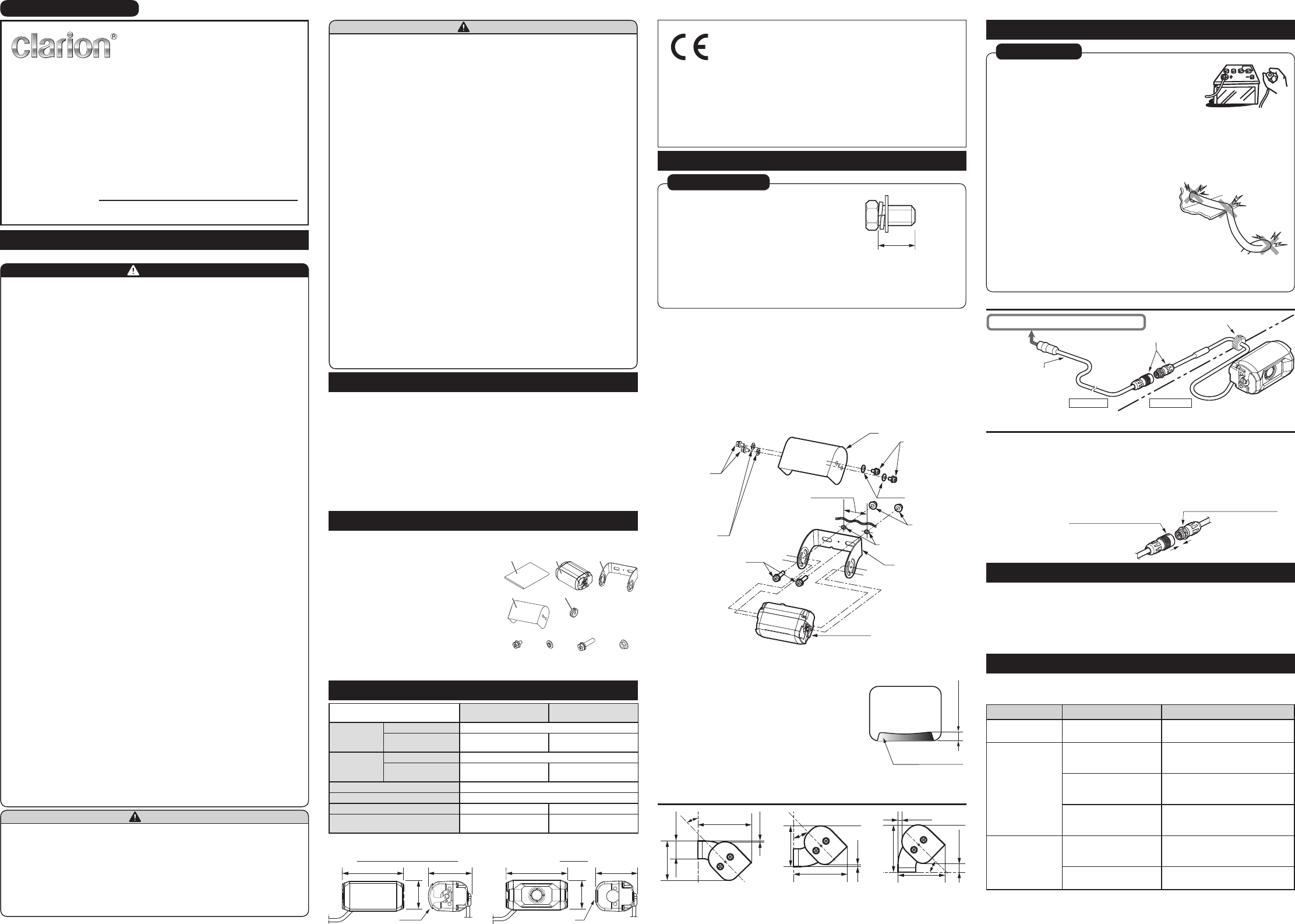
Use a protective tube or the enclosed grommet etc. to
protect the metallic parts of the routing holes, cross-
sections of the metal plate and parts of the cables that
are easily cut. In addition, lay the cables without damaging
them such as by twisting or bending them strongly as this
will result in internal short-circuiting. Be careful not to
scratch the outer skin as this will damage the waterproof
property.
For the power supply (camera power / shutter drive
power), use only the power supplied by the special EUC
box or monitor. Never supply power directly by connecting to a power supply line such as the
vehicle battery as this will result in a malfunction, fire, electric shock or accident due to an over-
voltage or over-current.
Wiring Precautions
Wiring example
Special waterproof
relay cable
(sold separately)
Connect the connectors properly.
Car Exterior
Car Interior
5Grommet (with notch)
Connect to the special camera ECU box or monitor.
Connection procedure for special waterproof relay cable (sold separately)
1
Align the arrow mark on the relay cable to the
mark on the camera cable
to insert the connector.
2
Pull the cable lightly to make sure that the connector is locked properly.
mark on the camera cable
Do not pull or bend the connected part with a force of 30 N or higher.
The connector may be damaged if an excessive load is applied.
Arrow mark on the relay cable
CLEANING THE CAMERA
Do not use benzine, thinner, or alcohols.
Do not wipe the camera with a cleaner that contains polishing powder etc. This may result in scratches
on the camera.
If the surface glass area is stained, wipe lightly with a soft and wet cloth etc. Scratches may occur if
you rub the camera strongly with a dry cloth.
If the surface glass area is stained, you can clean it by opening and closing the shutter with your hands.
When you open and close the shutter by hand, the shutter may not close completely sometimes. In this
case, operate the shutter to return it to the original position.
TROUBLESHOOTING
The following situations may not be malfunctions. Check the following one more time before sending the
camera for repair. Contact the dealer where the product was purchased if you have any questions or if
you still cannot resolve the problem.
Symptom Possible reasons Remedy
There is no image Incomplete wiring Check the connections and connect the
camera correctly.
Image quality is bad Surface glass area is stained Wipe lightly with a soft and wet cloth etc.
Note that scratches may occur if you rub
the camera strongly with a dry cloth.
The lens is exposed to sunlight
or the headlight from another
vehicle
The camera will return to normal if the
light shining on the lens disappears.
Surrounding is too dark Image quality deteriorates at night or in
dark places. The image returns to normal
when it brightens up.
Shutter does not open The area is constricted by
obstructions such as rubbish
etc.
Remove the obstructions. Note that the
shutter may be damaged if the obstruction
is removed unreasonably then.
Snow, ice, etc. is stuck to the
camera
Melt the snow, ice, etc., first before use.
2 3
4 5
1
6 7 98
Rear bumper or
rear end of the vehicle
approx. 7 mm
Monitor screen
English

Brauchen Sie Hilfe? Stellen Sie Ihre Frage.

Forenregeln

Missbrauch melden von Frage und/oder Antwort

Libble nimmt den Missbrauch seiner Dienste sehr ernst. Wir setzen uns dafür ein, derartige Missbrauchsfälle gemäß den Gesetzen Ihres Heimatlandes zu behandeln. Wenn Sie eine Meldung übermitteln, überprüfen wir Ihre Informationen und ergreifen entsprechende Maßnahmen. Wir melden uns nur dann wieder bei Ihnen, wenn wir weitere Einzelheiten wissen müssen oder weitere Informationen für Sie haben.

Art des Missbrauchs:

Zum Beispiel antisemitische Inhalte, rassistische Inhalte oder Material, das zu einer Gewalttat führen könnte.

Beispielsweise eine Kreditkartennummer, persönliche Identifikationsnummer oder unveröffentlichte Privatadresse. Beachten Sie, dass E-Mail-Adressen und der vollständige Name nicht als private Informationen angesehen werden.

Forenregeln

Um zu sinnvolle Fragen zu kommen halten Sie sich bitte an folgende Spielregeln:

Neu registrieren

Registrieren auf E - Mails für Clarion CC-6500E wenn:


Sie erhalten eine E-Mail, um sich für eine oder beide Optionen anzumelden.


Das Handbuch wird per E-Mail gesendet. Überprüfen Sie ihre E-Mail.

Wenn Sie innerhalb von 15 Minuten keine E-Mail mit dem Handbuch erhalten haben, kann es sein, dass Sie eine falsche E-Mail-Adresse eingegeben haben oder dass Ihr ISP eine maximale Größe eingestellt hat, um E-Mails zu erhalten, die kleiner als die Größe des Handbuchs sind.

Ihre Frage wurde zu diesem Forum hinzugefügt

Möchten Sie eine E-Mail erhalten, wenn neue Antworten und Fragen veröffentlicht werden? Geben Sie bitte Ihre Email-Adresse ein.


Info