HOW TO INST
How to at
Precautions for attachment
Be sure to use the specified screws when attaching the
receiver. Use of other screws may result in malfunction.
Precautions for attachment
1
Please install the receiver at stable position according to the
following diagram.
!
Rotate the threaded portion of the antenna clockwise and fix
the antenna securely to the receiver to prevent loosening.
5
Mounting brackets
7
Self tapping screws
(
5 mm x 16 mm)
(Four places)
6
with built-in washer
(M5 mm x 8 mm)
(Four places)
117 mm
45 mm
How to mount t
CAUTION
Neve
so may i
resulting
Avoid mo
dir
T
mou
it is n
Be su
any s
hexa
not un
en
ca
scr
1
Make a hole (2 places) for mounting the bracket in the
chassis and fix the bracket securely with the
$
hexagon
head bolts with built-in washer and flanged nuts.
2
Push-fit the gasket boss (2 places) into the guide hole from
inside the bracket.
3
Temporarily fix the camera in 4 places (a) with the
#
hexagon head bolts with built-in washer.
4
Using tools such as needle nose pliers, rotate the threaded
portion of the antenna clockwise and fix the antenna
securely to the camera to prevent loosening.
5
Temporarily fix the antenna bracket in 1 place (b) with the
#
hexagon head bolt with built-in washer so that the angle
of the antenna is controlled.
6
Install the wiring. (Refer to WIRING AND CONNECTIONS)
7
Adjust the mounting angle of the camera so that the rear
bumper or back end of the vehicle appears in the monitor
and tighten the bolts (a) to fix securely. (See diagram below)
Rear bumper or rear end of the vehicle
Monitor screen
The recommended guideline is approximately
1/10 of the monitor's overall height.
8
Adjust the antenna angle for optimal signal reception and
tighten the bolt (b) to fix securely.
P
Wh
the pr
If the c
column.
Pairing Switch Operation
•S
Th
•P
Enter
Th
pai
selection screen
Th
pai
the pairing
The pairing selection
scr
(No compat
was f
Advice
You cannot pair an already paired camera with another receiver.
Once paired, the pairing information is saved when the power is
If repeated searching fails to find the device you want to pair, it may
be due to poor radio wave reception. Replace the antenna on the
receiver with the optional long antenna and try again.
If the connected camera is replaced after pairing, Step 2 changes to
Turn on the replacement camera and connect the antenna.
Press the pairing switch while the camera image is displayed.
Th
Press and hold the pairing switch for at least 3 seconds while the
[Pairing changeover] screen is displayed.
Th
Repeat Search
Che
the antenna is c
to [ Search aga
switch for at leas
Searching sta
1
Turn on the power.
The [Clarion
scr
the s
sequence.
2
When the [Connecting]
screen appears, press and
hold the pairing switch for at
least 3 seconds.
Th
pai
appears.
Th
for a c
the search
the pairing
screen
3
Short-press the pairing
switch to point the cursor
to the camera number you
want to pair and press the
pairing switch for at least 3
seconds.
Th
is connect
camera sc
Advice
If the camera you want to pair does not appear
on the pairing selection screen or if the pairing
selection screen is not displayed, follow the steps
on the right to repeat the search.
If multiple camera numbers appear and you do
not know which to choose, select each number
in turn to find the right one.
4
If there is no problem with
the displayed camera
image, short-press the
pairing switch to point the
cursor to [Connect] and
press the pairing switch for
at least 3 seconds.
[Connect
fro
onl
is di
completed
Advice
If a different screen is displayed, short-press the pairing
switch to point the cursor to [Cancel] and press the pairing
switch for at least 3 seconds.
Se
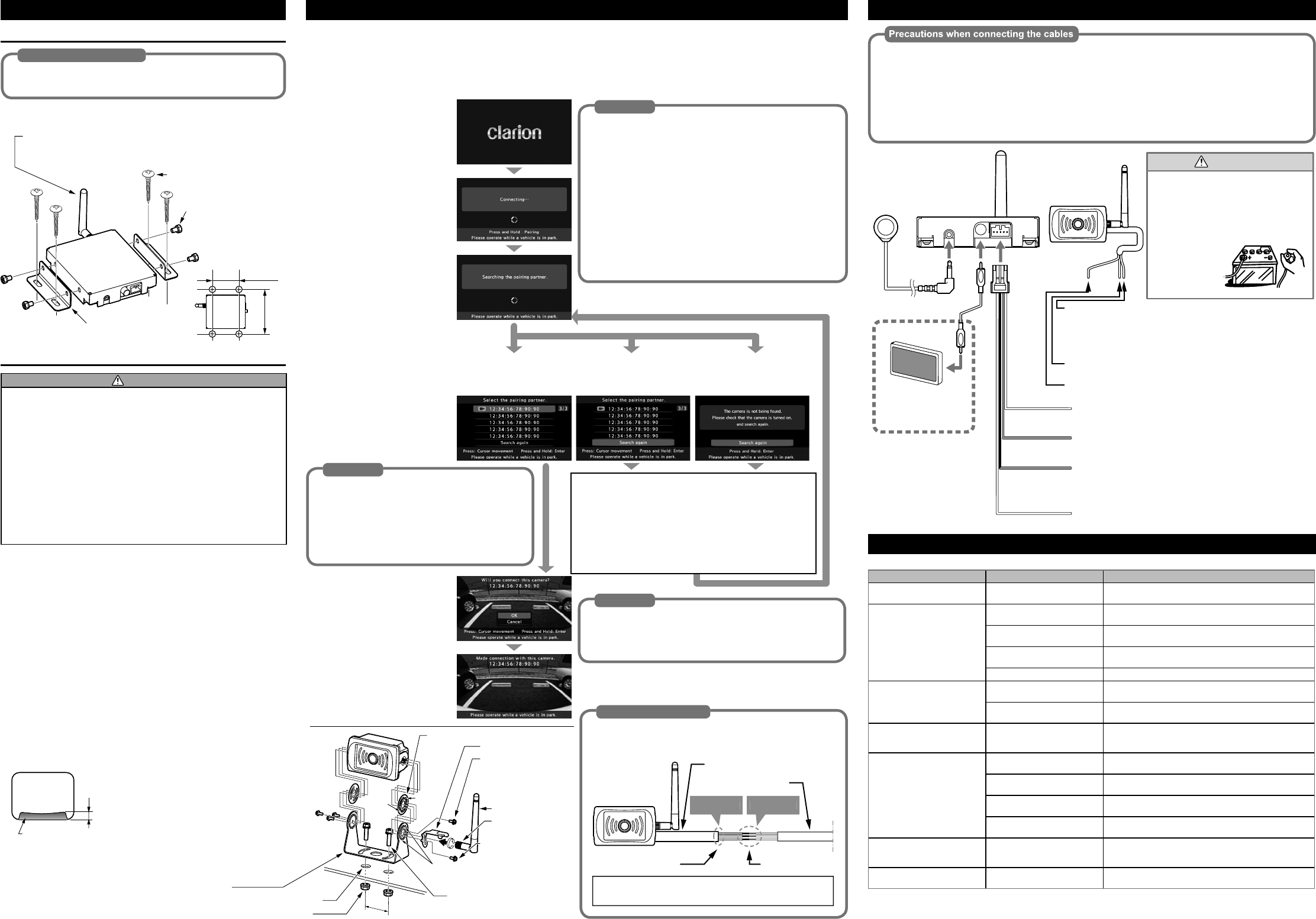
WIRING AND C
When the power cable (red) of the camera/transmitter is connected to the ACC line, connect the
orange/white cable from the receiver to the ACC line along with the ACC signal (red).
If there is no ACC power for the transmitter, connect the camera/transmitter's red cable to the
parking light line. At the same time, be sure to connect the orange/white cable from the receiver to
the parking light line. In this case, the camera image is displayed only when the driver turns on the
To prevent short-circuiting, check the connections again before connecting the battery.
Red Black
Red
Orange
with white stripe
Purple
with white stripe
Black
ACC+
Connect to a positive power supply that can be turned on and
off with the ignition key
Camera connection confirmation cable
Connect to a positive power supply where the camera red wire
is connected.
Reverse+
Connect to the reverse line which will have +12V/24V while in
reverse gear
NOTE: Please connect to
image will be ready to display all the time.
Ground (Negative)
Connect to chassis ground.
ACC+ / Parking light+
Connect to the positive power supply that can be turned on and off
with the ignition key
NOTE: When you connect the red cable to the Parking light lne,
the parking lights would need to be on in order for the camera to
work and the camera image will be ready to display all the time.
Ground (Negative)
Connect to chassis groud.
This wire is not used.
●
Do not connect the power cable (red)
of either the transmitter or the receiver
to the +B line (permanent power
supply) as this may lead to a flat battery
●
Disconnect the negative terminal of the
battery before connecting the cables.
Failure to do so may lead to electric
shock or injury due to short-circuit. It
may also lead
to damage to
the system
components
due to
short-circuit.
CAU
External monitor
(sold separately)
Example of monitor
combination
switch
Camera
with transmitter
(CC-3500)
Receiver
(EE-2178)
TROUBLESHOOTING
Th
Symptom Cause Measure
There is no image (Nothing appears
on the monitor)
The receiver is not connected
correctly
Check the receiver’s connections and connect the receiver
correctly
There is no image (“Connecting…” is
continuously displayed on the monitor)
The camera is not connected correctly Check the camera’s connections and connect the camera
correctly
The surrounding radio wave signal
strength is weak
Move to a different place and check if the image appears
The radio wave reception of the
camera is poor
Change the position of the antenna on the receiver or replace with the
optional long antenna and check again.
There is no paired camera around Press the pairing switch for at least 3 seconds to complete pairing.
The image cuts out (“The video has
been stopped” appears)
The surrounding radio wave signal
strength is weak
Move to a different place and check if the image appears
The radio wave reception of the
camera is poor
Change the position of the antenna on the receiver or replace with the
optional long antenna and check again.
“Communication has been
disconnected.” appears on the
monitor
The camera has been disconnected Depending on the state of the surrounding radio waves, the
camera is disconnected. Reconnection is automatic.
The camera you want to pair does not
appear on the pairing selection screen
The camera is not connected correctly Check the camera’s connections and connect the camera
correctly
The surrounding radio wave signal
strength is weak
Move to a different place and check if the image appears
The radio wave reception of the
camera is poor
Change the position of the antenna on the receiver or replace with the
optional long antenna and check again.
The camera you want to pair has been
paired with another receiver.
Turn off the receiver to which the camera you want to pair is
connected and wait a while (30 seconds) before pairing again.
“The button has been pressed for
more than 10 seconds.” appears
The pairing switch has been pressed
for more than 10 seconds
Check that there is nothing on top of the pairing switch pressing it
down, and then press the pairing switch once to return to the original
screen.
The pairing switch does not respond
when pressed
The pairing switch is not connected
correctly
Check the pairing switch’s connections and connect the button
correctly.
(a)
(a)
(a)
(b)
(a)
45 mm
¥
Antenna bracket
0
Mounting bracket
%
Flanged nuts (M5 mm) (Two places)
Vehicle side : 5.5 mm holes (Two places)
Boss
Boss
!
Antenna
@
Gaskets (Two places)
Threaded portion
of the antenna
#
bo
wa
(M3 m
(F)
#
bo
wa
(M3 m
(On)
$
built-in washer (M5 mm x
8 mm) (Two places)
Guide holes
Wiring Precaution
Please carry out waterproof treatment on hookup point
between camera power cable and vehicle wiring as per
As we
the e