ILLUSTRA
ILLUSTRA
ILLUSTRA
INTRODUCTION
Dear customer
Y
your experiences with this quality product will be pleasant ones. The RF LED panel is a multi-purpose LED
solution: it is suitable for xation to walls and ceilings and can easily be operated using the remote control.
Important notice:
Prior to
operate
later on.
TECHNICAL SPECIFICA
• Input voltage: 1
• LED QTY
• LED power: 40W max with external LED driver
• LED Lumen: max. 3400 Lm
• Color temperature: W
• Operation temperature: -10°C~+40°C
• IP grade: IP20 (indoor use only
• Material: Frosted light diffuser with aluminum frame
• Size: 1200 x 300 x 8 mm
• Weight: 2355g (panel only) – 2570g (including controller)
SAFETY INSTRUCTIONS
• Check if product in condition complete parts as in
chapter “Package contents”) when opening the package.
• Some
requirements in your country
• This product is only suitable for indoor use.
• Do not immerse the product in water
• Do not cover the product, make sure there is sufcient ventilation. Keep at least 20cm distance from
inammable objects, or heat sources.
• Don’t place in locations with extremely high/low temperatures.
• Never touch the plug contacts with sharp or metal objects.
• Make sure that cables cannot cause a trip hazard.
• Use only the original power supply and original accessories.
• Do
considerable
will be void.
• If the unit is not properly installed or operated DreamLED® cannot accept liability
P
See illustration I
1. Warm white LED panel
2.
3.
4.
5.
6.
• 90° mounting parts for wall & ceiling use: 4x S-size (wall mount) – 4x L-size (ceiling mount)
• 6x screw
• 6x wall plug
• 4x clip
• 4x Tie-rips
USE OF THE REMOTE CONTROL
See illustration II
Note:
* The remote control is not waterproof.
*
*
saved.
1. T
Note: One remote
remote
and
with the remote control has been successful.
2. T
3.
4.
5.
6.
INST
IMPORTA turn OFF the power before starting with the installation!
Remove all parts that are already attached to the panel and which are not needed anymore.
There are 5 possible ways to install the DreamLED RF LED panel:
1. Built-in ceiling xation
a) Remove the ceiling part where the LED panel will be placed.
b) Install the LED
parts. There should be at least 3-5 cm free space around the LED for efcient operation!
c) Insert the LED panel in the ceiling.
d) Fix the LED panel tightly and turn the power back on.
2. Clip-in ceiling xation
a) Add the xation clips by screwing them to the back of the LED panel.
b) Remove the ceiling part where the LED panel will be placed.
c) Install
parts. There should be at least 3-5 cm free space around the LED for efcient operation!
d) Open the clips and insert the LED panel in the ceiling.
e) Release the clips so that the LED panel “clicks” onto the ceiling.
f) T
3.
a) Mark the position of the 2 screws and drill the 2 holes.
b) Insert the plugs into the drilled holes.
c) Screw the pendant holders into the plugs.
d) Run the suspension cables through the holes into the pendant holders.
e) Attach
lifting it up.
f) Lower the RF Panel so the suspension cables are tight to see if it is equally levelled.
g) T
h)
placed
be at least 3-5 cm free space around the LED for efcient operation!
4.
a) Mark the 4 screw positions on the ceiling.
b) Drill holes in the marked locations.
c) Add wall plugs into the holes.
d) Put the screws into the plugs.
e) Place the LED panel onto the screws and slide to x tightly
f) Install the
placed on top using L-size mounts ) or
There should be at least 3-5 cm free space around the LED for efcient operation!
5.
a) Mark the 4 screw positions (or only the 2 at the top) on the wall.
b) Drill holes in the marked locations.
c) Add wall plugs into the holes.
d) Put the screws into the plugs.
e) Attach the wall mounts (S-Size) by screwing them onto the RF Panel
f) Place the LED panel onto the screws and slide to x tightly
g) Install the LED
placed out
free space around the LED for efcient operation!
CARE AND
• Shut off using the main power switch before cleaning.
• Do not use any cleaners with chemicals, solvents or harsh abrasives. Use only a dry
wipe carefully
SUPPORT
For
support@dream-led.eu.
GUARANTEE
Copyright ® . DreamLE® a registered TE-Group DreamLED® brand
stands for ® warrants this
product against all defects in material and workmanship for
purchase ® under this
warranty can be downloaded from the website: www
GB NL
USER’S MANUAL DFR
DECLARA
OU T P UT
IN P UT
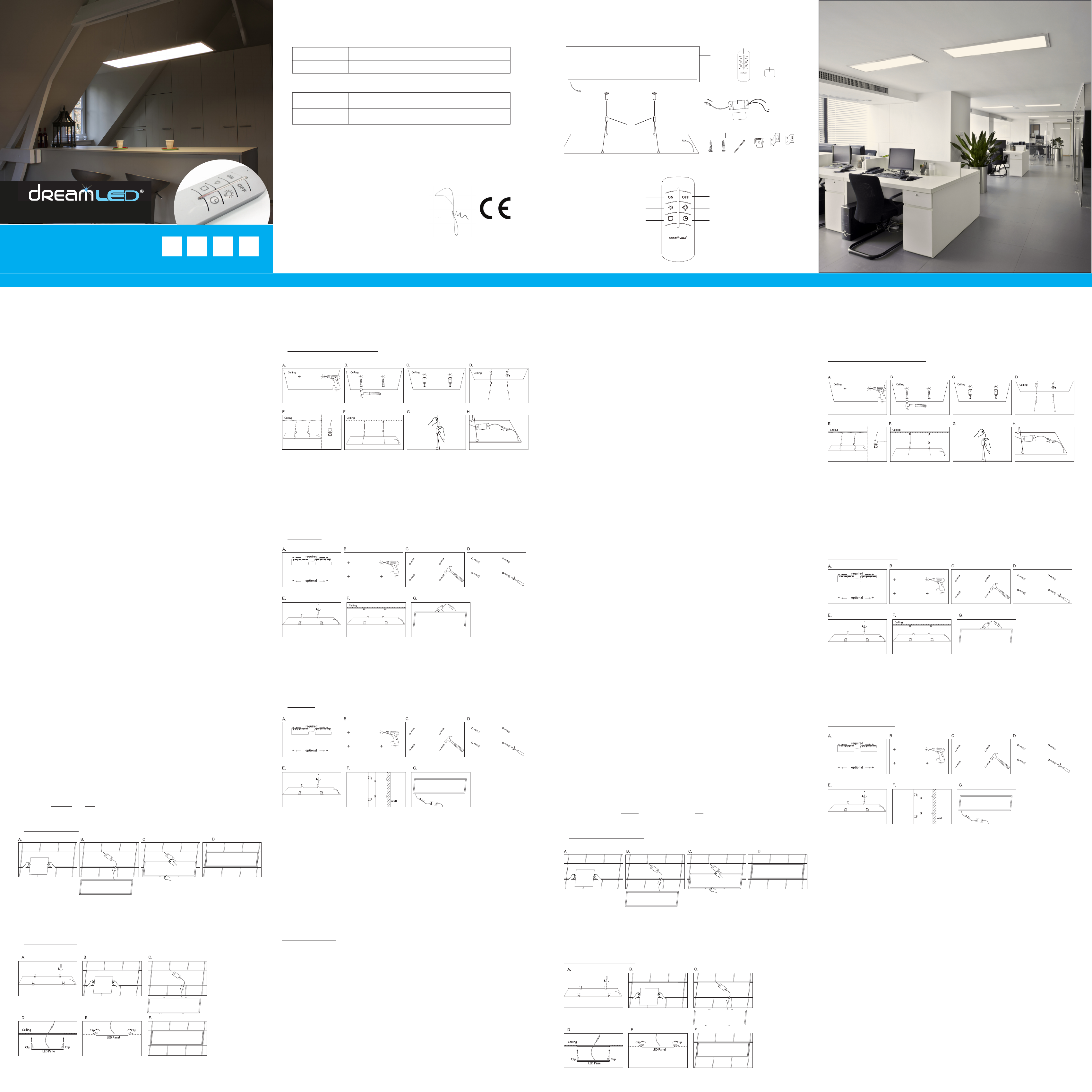
ILLUSTRA TIONS
ILLUSTRA TION I ILLUSTRA TION II
INST ALLA TION
IMPORT ANT : A LW A YS turn OFF the power before starting with the installation!
Remove all parts that are already attached to the panel and which are not needed anymore.
There are 5 possible ways to install the DreamLED RF LED panel:
1.
OUTP UT
INPUT
A. B. C. D.
a) Remove the ceiling part where the LED panel will be placed.
b) Install the LED driver by connecting it to the power supply and place it on top of the LED panel or ceiling
c) Insert the LED panel in the ceiling.
d) Fix the LED panel tightly and turn the power back on.
2.
A. B. C.
D.
Ceiling
Clip
LED Panel
E. F .
Clip
LED Panel
Clip Clip
a)
b) Remove the ceiling part where the LED panel will be placed.
c) Install the LED driver by connecting it to the power supply and place it on top of the LED panel or ceiling
d) Open the clips and insert the LED panel in the ceiling.
e) Release the clips so that the LED panel “clicks” onto the ceiling.
f) T urn the power back on.
3. Suspension on ceiling (hanging way)
A. B. C. D.
E. F . G. H.
C eiling C eiling C eiling
a) Fix the 4 bullet head nuts at the end of the steel wires to the LED panel.
b)
c)
into the holes.
d)
e)
f)
g)
“button” on the wire connection point on the pendant to release the wire and make it shorter or longer .
h) Install the LED driver by connecting it to the power supply and turn on the powe r . The LED driver can be
placed on top of the LED panel (out of sight) or it can be built-in inside or on top of the ceiling. There should
4. Ceiling mount
Ceiling
a) Mark the 4 screw positions on the ceiling.
b) Drill holes in the marked locations.
c) Add wall plugs into the holes.
d) Put the screws into the plugs.
e)
f) Install the LED driver by connecting it to the power supply and turn on the powe r . The LED driver can be
placed on top of the LED panel (out of sight, using L-size mounts ) or it can be built-in inside the ceiling.
5. W all mount
a) Mark the 4 screw positions (or only the 2 at the top) on the wall.
b) Drill holes in the marked locations.
c) Add wall plugs into the holes.
d) Put the screws into the plugs.
e) Place the LED panel onto the screws, using the S-size mounts
f) Install the LED driver by connecting it to the power supply and turn on the powe r . The LED driver can be
placed out of sight using the long cable or it can be built-in inside the wall. There should be at least 3-5 cm
free space aroun
CARE AND CLEANING
• Shut of f using the main power switch before cleaning.
• Do not use any cleaners with chemicals, solvents or harsh abrasives. Use only a dry , soft cloth to dust or
wipe carefull y .
SUPPORT
: t c a t n o c d l u o h s u o y , t c u d o r p s i h t g n i n r e c n o c s t s e u q e r n r u t e r d n a s n o i t s e u q l a c i n h c e t , n o i t a m r o f n i e r o m r o F
support@dream-led.eu.
GUARANTEE
Copyright © DreamLED ® . DreamLED ® is a registered trademark of TE-Group NV . The DreamLED ® brand
stands for superior product quality and outstanding customer service. That is why DreamLED ® warrants this
product against all defects in material and workmanship for a period of two (2) years from the date of original
purchase of the product. The terms of this guarantee and the extent of responsibility of DreamLED ® under this
warranty can be downloaded from the website: www .dream-led.eu.
T
OUTPUT
IT
1
2
4
3
5
6
x6 x6 x4
x4 x4 x4
+ : brown or red = L
- : blue = N
L-size S-size
T
for driver
RF antenna
1 2
3 4
6 5
OU T PUT
IN P U T
O UT P U T
INPUT
OUTPUT
I N PUT
Ceiling
C eiling
O U T P U T
I N P U T
wall
A. B. C.
E. F. G .
6 9 5 15 4 14 13 12 8 11 7 10 16 22 25 21 20 30 19 29 18 28 17 24 27 23 26
required
optional
D.
A. B. C.
E. F. G .
6 9 5 15 4 14 13 12 8 11 7 10 16 22 25 21 20 30 19 29 18 28 17 24 27 23 26
required
optional
D.
Ceiling
Manual/DREAM-LED/RF LED P
Copyright © DREAM-LED
INLEIDING
Beste klant,
Gefeliciteerd met de aankoop van uw DREAMLED RF LED P We danken u voor deze aankoop
en aangename ervaringen zal kwaliteitsproduct. Het RF is een
multifunctionele
kan makkelijk bediend worden met de bijgeleverde afstandsbediening.
Belangrijk bericht:
V
uw LED
nog kan raadplegen.
TECHNISCHE SPECIFICA
• Ingangsspanning: 1
•
• LED-vermogen: 40W max. met externe LED driver
• LED Lumen: max. 3400 Lm
• Kleurtemperatuur: W
• Werktemperatuur: -10°C~+40°C
• IP-klasse: IP20 (uitsluitend voor binnengebruik, klasse I)
• Materiaal: Matte lichtverdeler met aluminium frame
•
• Gewicht: 2355g (enkel paneel) – 2570g (inclusief controller)
VEILIGHEIDSINSTRUCTIES
• Controleer het product en staat het openen
verpakking. U kan alle onderdelen terugvinden in het hoofdstuk “V
• In
Wij raden u aan om de wetgeving en vereisten van uw land hieromtrent te raadplegen.
• Dit product is enkel geschikt voor gebruik binnenshuis.
• Gebruik het product niet in de nabijheid van water
• Dek
objecten of hittebronnen.
• Plaats het toestel niet op locaties met extreem hoge of lage temperaturen.
• Raak nooit de elektrische contacten aan met scherpe of metalen objecten.
• Berg de kabels zodanig op dat er geen risico is op struikelen.
• Gebruik enkel de originele stroomvoorziening en originele accessoires.
• Gebruik
openen
aan om het toestel enkel door een gekwaliceerde expert te laten herstellen, anders vervalt de garantie.
• A
ls ®
VERP
Zie illustratie I
1. Warm wit LED paneel
2. RF afstandsbediening + batterij
3. LED driver + DC adapter (2-in-1) + tape
4. Velcro tape met industriële tape op de achterzijde (voor de afstandsbediening)
5. Ophangsysteem voor plafonds met stalen draden
6. Montage-onderdelen :
• 90° muur- plafondbevestiging: S 4x
(plafondbevestiging)
• 6x schroef
• 6x muur plug
• 4x clip
• 4x T
GEBRUIK V
Zie illustratie II
Opmerking:
* De afstandsbediening is niet waterdicht.
* Gebruik de afstandsbediening niet in ruimtes met temperaturen boven 50°C.
* Als het LED
laatste instelling opgeslagen worden.
1. Het paneel inschakelen
Opmerking:
max. 20~25
langer dan 8 seconden. Zet de stroom meteen weer op en houd onmiddellijk de
RF
2. Het paneel uitschakelen.
3. De lichtintensiteit verminderen (geleidelijk van 100% tot 10%)
4. De lichtintensiteit vermeerderen (geleidelijk van 10 % tot 100%)
5. Standaardinstellingen (4 intensiteiten): 3400Lm / 2890Lm / 1615Lm / 935Lm
6. De automatische uitschakel-modus na 30 seconden activeren
INST
BELANGRIJK: Schakel
V
Er zijn 5 mogelijke manieren om het DreamLED RF LED P
1.
a) V
b) Installeer driver door deze te verbinden met de stroomvoorziening. Plaats deze bovenop het
LED paneel of
werking van uw paneel.
c) Voeg het LED paneel in de voorziene ruimte in.
d) Bevestig het LED paneel goed en zet de stroom terug aan.
2. Klik-in plafond bevestiging
a) Schroef bevestigingsclips op de (de schroeven zijn reeds aan het
paneel bevestigd)
b) V
c) Installeer de LED driver door deze te verbinden met de stroomvoorziening. Plaats deze bovenop het
LED paneel of
werking van uw paneel.
d) Open de clips en voeg het LED paneel in de voorziene ruimte in.
e) Laat de clips los zodat het LED paneel vastklikt in het plafond.
f) Zet de stroom terug aan.
3. Ophanging aan het plafond (hangend)
a) Markeer de positie voor de 2 schroeven en boor de 2 gaten.
b) Steek de pluggen in de geboorde gaten.
c) Schroef de hanger-houders in de pluggen.
d) Haal de ophangkabels door de gaten in de hanger-houders.
e) Bevestig het RF Panel aan
terwijl je het paneel optilt..
f) Laat het
hangt.
g) Om
.
h) Bevestig
worden
werking van uw paneel.
4. Bevestiging tegen plafond
a) Markeer de positie waar de 4 schroeven moeten komen op de muur
b) Boor gaten op deze 4 posities.
c) Steek muurpluggen in de geboorde gaten.
d) Draai de schroeven in de muurpluggen.
e) Plaats het LED paneel op de schroeven en schuif het paneel in positie.
f) Installeer de LED driver door hem te verbinden met de stroomvoorziening en zet de stroom aan. De
LED maat
L bevestigingsonderdelen) of
ruimte zijn voor de efciënte werking van uw paneel.
5. Bevestiging aan de muur
a) Markeer de positie waar de 4 schroeven moeten komen (of enkel de 2 bovenste) op het plafond.
b) Boor gaten op deze 4 posities.
c) Voeg muurpluggen in de geboorde gaten.
d) Steek de schroeven in de muurpluggen.
a) Schroef de muurbevestigingen (Maat S) vast aan het RF Panel
e) Plaats het LED paneel op de schroeven en glijd het paneel in positie.
f) Installeer de LED driver
driver
minstens 3-5 cm vrije ruimte zijn voor de efciënte werking van uw paneel.
ONDERHOUD
• Zorg dat de stroom helemaal uitstaat alvorens te poetsen.
• Gebruik met chemicaliën, Gebruik
droge zachte doek om voorzichtig te reinigen of af te stoffen.
KLANTENONDERSTEUNING
V
contact op te nemen met support@dream-led.eu.
GARANTIE
Copyright © DreamLED® . DreamLED® is een gedeponeerd handelsmerk van TE-Group NV Het merk
DreamLED® staat voor producten van superieure kwaliteit en een uitstekende klantenservice. Daarom
garandeert ® dat
twee
de ® onder
website: www
Hereby
Par la présente,
Company:
Entreprise:
Address:
Adresse:
declare that the following equipment:
déclare que le dispositif suivant :
Product name:
Nom du produit:
Product type:
T
conforms with the following safety requirements of the directives 201
2014/35/EU, 2014/30/EU and 2004/108/EC. Conformity is guaranteed by the
CE-symbol.
est conforme aux exigences de sécurité suivantes des directives 201
2014/35/EU, 2014/30/EU and 2004/108/EC. La conformité est garantie par le
symbole CE.
This product has been tested against following standards and specications,
applying versions valid in December 2016.
Ce
les versions valides en Décembre 2016.
EN 60598-1:2015
EN 60598-2:1989
EN 55015:2013
EN 61547:2009
EN 61000-3-2:2014
EN 61000-3-3:2013
Joseph van Oosterum, CEO TE-Group NV
Authorized Signature, December 2016, Kapellen
TE-Group NV
Kapelsestraat 61, 2950 Kapellen, Belgium
DreamLED RF LED P
RFLP-120
OU T P UT
I N P UT
ILLUSTRA TIONS
ILLUSTRA TION I ILLUSTRA TION II
INST ALLA TION
IMPORT ANT : A LW A YS turn OFF the power before starting with the installation!
Remove all parts that are already attached to the panel and which are not needed anymore.
There are 5 possible ways to install the DreamLED RF LED panel:
1.
OUTPUT
INPUT
A. B. C. D.
a) Remove the ceiling part where the LED panel will be placed.
b) Install the LED driver by connecting it to the power supply and place it on top of the LED panel or ceiling
c) Insert the LED panel in the ceiling.
d) Fix the LED panel tightly and turn the power back on.
2.
A. B. C.
D.
Ceiling
Clip
LED Panel
E. F .
Clip
LED Panel
Clip Clip
a)
b) Remove the ceiling part where the LED panel will be placed.
c) Install the LED driver by connecting it to the power supply and place it on top of the LED panel or ceiling
d) Open the clips and insert the LED panel in the ceiling.
e) Release the clips so that the LED panel “clicks” onto the ceiling.
f) T urn the power back on.
3. Suspension on ceiling (hanging way)
A. B. C. D.
E. F . G. H.
C eiling C eiling C eiling
a) Fix the 4 bullet head nuts at the end of the steel wires to the LED panel.
b)
c)
into the holes.
d)
e)
f)
g)
“button” on the wire connection point on the pendant to release the wire and make it shorter or longer .
h) Install the LED driver by connecting it to the power supply and turn on the powe r . The LED driver can be
placed on top of the LED panel (out of sight) or it can be built-in inside or on top of the ceiling. There should
4. Ceiling mount
Ceiling
a) Mark the 4 screw positions on the ceiling.
b) Drill holes in the marked locations.
c) Add wall plugs into the holes.
d) Put the screws into the plugs.
e)
f) Install the LED driver by connecting it to the power supply and turn on the powe r . The LED driver can be
placed on top of the LED panel (out of sight, using L-size mounts ) or it can be built-in inside the ceiling.
5. W all mount
a) Mark the 4 screw positions (or only the 2 at the top) on the wall.
b) Drill holes in the marked locations.
c) Add wall plugs into the holes.
d) Put the screws into the plugs.
e) Place the LED panel onto the screws, using the S-size mounts
f) Install the LED driver by connecting it to the power supply and turn on the powe r . The LED driver can be
placed out of sight using the long cable or it can be built-in inside the wall. There should be at least 3-5 cm
free space aroun
CARE AND CLEANING
• Shut of f using the main power switch before cleaning.
• Do not use any cleaners with chemicals, solvents or harsh abrasives. Use only a dry , soft cloth to dust or
wipe carefull y .
SUPPORT
: t c a t n o c d l u o h s u o y , t c u d o r p s i h t g n i n r e c n o c s t s e u q e r n r u t e r d n a s n o i t s e u q l a c i n h c e t , n o i t a m r o f n i e r o m r o F
support@dream-led.eu.
GUARANTEE
Copyright © DreamLED ® . DreamLED ® is a registered trademark of TE-Group NV . The DreamLED ® brand
stands for superior product quality and outstanding customer service. That is why DreamLED ® warrants this
product against all defects in material and workmanship for a period of two (2) years from the date of original
purchase of the product. The terms of this guarantee and the extent of responsibility of DreamLED ® under this
warranty can be downloaded from the website: www .dream-led.eu.
T APE
OUT P U T
I T U P N
1
2
4
3
5
6
x6 x6 x4
x4 x4 x4
+ : br o wn or r ed = L
- : blue = N
L -siz e S -siz e
T APE
f or dr iv er
RF an t enna
1 2
3 4
6
OUTPUT
INP UT
O UT P U T
INPU T
OUTPUT
INPUT
Ceiling
C eiling
O U T P U T
I N P U T
wall
A. B. C.
E. F. G .
6 9 5 15 4 14 13 12 8 11 7 10 16 22 25 21 20 30 19 29 18 28 17 24 27 23 26
required
optional
D.
A. B. C.
E. F. G .
6 9 5 15 4 14 13 12 8 11 7 10 16 22 25 21 20 30 19 29 18 28 17 24 27 23 26
required
optional
D.
Ceiling
RF LED P