7 Wiring diagram
RTRt-E 525 80/81
RTRt-E 525 84/86
8 Dimensions
4. Important notes
• The Triac is not protected. Overload or short-circuit of the load will damage the Triac.
• The disconnection of the load takes place at current-zero, so that a contactor directly can be controlled without
any supplementary steps.
• During the ON period the Triac is conductive permanent. There happens no phase section.
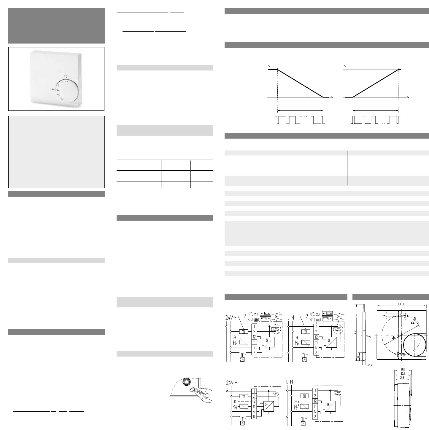
5. Function diagram
Characteristic of impulse pause ratio depending on temperature
plug-in jumper – right side: “NC”, heating plug-in jumper – left side “NO”, cooling
6. Technical data
Type RTRt-E 525 80/81/84/86
Article No. 515 1901 515 1905 515 1911/14 515 1903
Operating voltage AC 24 V (20…30 V), 50/60 Hz AC 230V (195…253 V), 50/60 Hz
Switching current
permanent (see note) 0…1,2 A (cosϕ = 1)* 0…0,8 A (cosϕ = 1)*
0…0,7 A (cosϕ = 0,6)* 0…0,5A (cosϕ = 0,6)*
short-time for 2 sec. max. 5 A max. 5 A
Number of actuators 5 (3 W electro thermal) 5 (3 W electro thermal)
each to be connected
Switching voltage corresponding to operating voltage
Temperature range 5 to 30°C
Range limitation inside setting knob
Temperature set-back approx. 3 K
Cycle period 5…10 min (sum of PWM ON and OFF times)
Output Triac
Temperature sensor integral
Remote sensor (optional) type F 190 021 (wall mounting)
type F 193 720 length 4 m
both extendable up to 50 m
Sensor characteristics 42kΩ at 20°C
26 kΩ at 30°C
Proportional band 1.5 K
Protection class of housing IP 30 insulated
Degree of protection II (see Warning!)
Ambient temperature –10…+40°C without condensation
Storage temperature –25…+65°C
Weight ~75 g
* Note: At reversed direction of efficiency (for RTRt-E 525 84 or jumper plugged left side for RTRt-E 525 80/81) and at operation without
remote sensor, the permanent switching current schould not exceed 0.5A!
temp.
rel. capacity / %
temp.
rel. capacity / %
Warning!
This unit must not be opened and installed except by au-
thorized persons and in compliance with the circuit dia-
gram provided inside the cover. It is mandatory in all work
on the unit to observe the current safety regulations.
In order to classify for protection class II it is necessary to
take adequate installation measures.
This separately mounted unit is designed for temperature
control exclusively in dry and closed rooms with standard
environment. The unit features radio-interference sup-
pression
in compliance with VDE 0875 T.14 and EN55014,
respectively and works according to operating principle
1 Y (EN 60730).
1. Applications
The electronic thermostat with Triac output can be
used for:
• Control of hot water heating systems in conjunction
with electrothermal actuators (closed or open de-
energised) such as hot water, convector or floor
heating systems.
• Electric convector, floor, ceiling and storage heat-
ing systems connected with contactor
• Night storage heating
• Air Conditioning equipment (cooling only)
Features
• Temperature set-back
• Direction of efficiency changeable for application of
actuators n/o or n/c
• Changing of heating/cooling mode
• Available variants
➩ mode selector switch comfort/set-back/automatic
➩ indication lamp “calling for heat”
➩ operating voltage AC 24 V or AC 230 V
• Remote sensor optional
• High life expectancy and noiseless due to
electronic load interruptor
2. Function description
Variant without mode selector switch
(Type RTRt-E 525 80/84/86)
Comfort temperature will be set by means of exter-
nally visible setting knob. Controller contact switches
the associated heath source until the set temperature
is reached.
3 Automatic mode
(via external timer)
The adjusted temperature at the setting knob will be
reduced of approx. 3°C when contact at terminal 8 is
closed.
Variant with mode selector switch
(Type RTRt-E 525 81)
r Permanent comfort
(day) temperature.
The required temperature can be adjusted at the set-
ting knob. Controller contact switches the associated
heat source until the set temperature is reached.
s
Permanent set-back temperature
The adjusted temperature at the setting knob is con-
tinuously reduced by about 3 °C.
3 Automatic mode
(via external timer)
The adjusted temperature at the setting knob will be
reduced of approx. 3°C when contact at terminal 8 is
closed.
Variant with indication lamp
This lamp indicates “controller calls for heat”
Heat demand of the controller
Via the incorporated Triac the heat source will be
switched in the form of pulses of varying lenght
(PWM). The length of the pulses depends on the dif-
ference between set and actual room temperature.
The sum of pulse and pause times can be approx. 5 to
10 minutes.
If there are large temperature differences, the con-
troller will switch ON or OFF permanent, e.g. when
changing over to temperature set-back mode.
Changing of direction of the efficiency
(only type RTRt-E 525 80/81
By means of the plug-in jumper there can be selected
the control of n/c actuators or n/o actuators. This
controller can also be used for “cooling only” applica-
tions.
Plug-in jumper for valves if valves
(right side of board) n/c
right side plugged n/c heating
(as-delivered condition)
left side plugged n/o cooling
Variant without plug-in jumper
(type RTRt-E 525 84/86)
Direction of efficiency : see wiring diagram inside cover.
3. Installation
The controller should be arranged in a place within
the room which:
• is easily accessible for operation
• is free from curtains, cupboards, shelves, etc.
• enables free air circulation
• is free from direct sun radiation
• is free from draughts (e.g. opening of windows and
doors)
• is not affected directly by the source of heat
• is not located on an external wall
• is located approx. 1,5 m above floor level
Mounting directly on conduit box or with adapter
frame ARA 1E.
Electric connection
Warning! Disconnect electric circuit from supply.
Proceed as follows:
• pull off temperature setting knob
• open screw
• remove housing cover
• make connection in compliance with wiring dia-
gram (see housing cover).
• watch notes
Remote Sensor
• Remove internal sensor as shown
• Connect external remote sensor to terminals 11 and
12 according to wiring diagram (inside cover)
• The sensor cable is
extendable up to a
lenght of max. 50 m.
Please use a two-core
230 V cable with a
cross section of 1.5 mm
2
.
The sensor cable (F 193 720) should be installed into
a protection tube (pocket). This facilitates later re-
placement.
Warning! Sensor cables carry operating voltage.
468 931 012 930-02
K
Installation and operating instructions
Electronic room temperature controller
with Triac output
RTRt-E 525 80 /81/ 84/86