Ferm 3
in the centre.
- Tighten down the bolts again.
- Slide the carriage in the direction of the loose head
and repeat the procedure. Then check again whether
the machine is level on the side of the fixed head and
continue until both sides of the machine are level.
5. During transport and unpacking, some litter will pro-
bably have landed on the turning lathe. Do not move
the carriage or the loose head before the bed has
been cleaned thoroughly.
4. ELECTRICAL CONNECTIONS
- Check whether the connecting voltage stated on the
type plate corresponds to the mains voltage. Machi-
nes with the indication of 400 Volts can simply be con-
nected to a voltage of 380 Volts.
- For connecting to another mains voltage, consult the
wiring diagram in the lid of the engine housing.
- Connect the machine to an earthed power source.
- The electric control box is situated behind the fixed
head.
- Put the control switch handle in the central position
and press the "power start" knob to engage the po-
wer. When the cs handle is in the foremost position,
the shaft turns to the left; when the handle is in the re-
ar position, the shaft turns to the right. If this is not the
case, switch off the power and change the wiring as in-
dicated in the wiring diagram.
- Stop the machine by placing the control switch in the
central position. When the reset knob is pressed the
machine will start again.
5. PUTTING INTO OPERATION
1. Before use, read the instructions for use carefully so
that you know how to adjust, operate, grease and
maintain the machine etc.
2. The machine is equipped with 2 V-belts which run fr-
om the engine to the bottom most, back pulley.
Check the tension of the V-belt before starting the
machine. If you press carefully on the V belt, you
should be able to press it in by approximately 1.5 cm. If
the V belt is too tight it can damage the bearing. Chan-
ge the tension, if necessary.
3. Before doing a test run, place the speed adjuster in the
lowest position and allow the machine to run for ap-
proximately 20 minutes. If the machine is working
normally, increase the speed step by step until the hig-
hest speed has been reached (feed lever in central po-
sition). Continually allow the machine to run for ap-
proximately 5 minutes by every speed.
The speed can only be changed if the engine is at
a complete standstill.
6. OPERATING HANDLES
(See Illustration 2)
FIXED HEAD
- By means of the handles 1 and 2 and the V-belts, the
speed of the fixed head can be adjusted in 2 steps, in-
creasing from 60 to 1,500 revolutions per minute, as
is shown in the "Spindle speed" table which is situated
on the front of the fixed head.
- The spindle can only be started and stopped using the
starting handle (11). When the handle is raised, the
spindle turns to the left; when the handle is lowered, it
turns to the right.
GEARBOX
- By means of handle (4) a choice can be made between
threading or turning. The left position is for the feed
shaft, the central position is neutral and the right posi-
tion is for the lead screw.
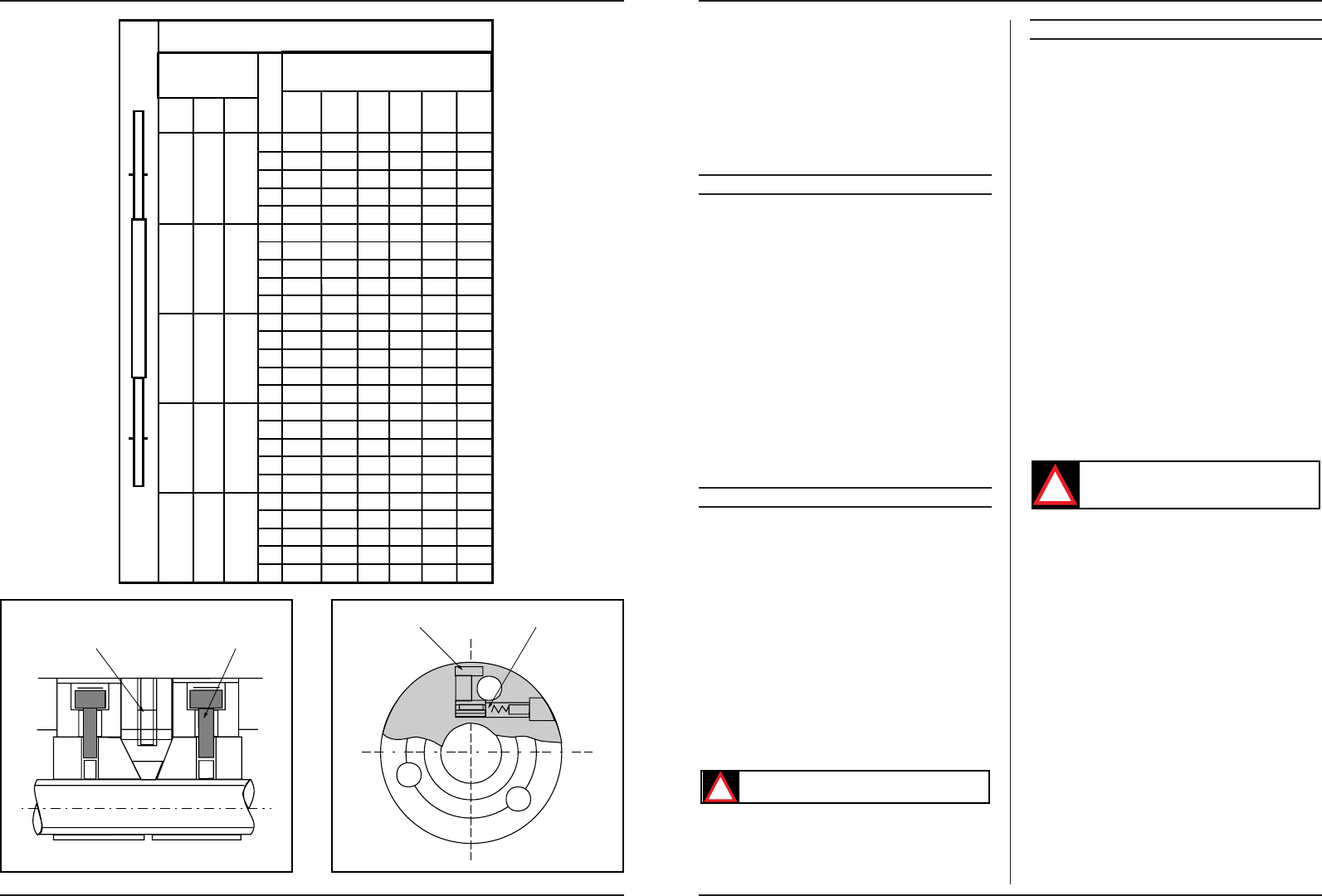
- By means of handles (5) and (6) the gearbox can be
operated. Handle (5) has five positions, handle (6) has
eight positions. Using these two handles, all kinds of
feeding speeds to the left of the fixed head can be ad-
justed (Illustration 3), and screw thread pitches (in-
ches) on the front of the fixed head (Illustration 4). By
means of the metric change wheels, metric screw th-
reads can also be adjusted with the two handles, using
the "conversion table" on the front of the fixed head
(Illustration 5).
Make sure that the spindle is at a complete
standstill before using one of the three handles
referred to above.
CARRIAGE
- Handwheel (7) is used to move the carriage by hand
over the bed.
- By means of the arm for the cross feed (19) the tool
holder can be turned in or out. It can be placed in its
entirety at any angle desired and can also be used for
cutting screw thread or applying a corner to a work-
piece.
- By means of the start/stop handle (11) the direction of
running of the spindle can be changed.
- The thread screw handle (9) is used for the lead screw
nuts during cutting of the screw thread.
- By means of the handle for the feed movement (8) a
choice can be made between feeding lengthwise or
crosswise. This handle has a protection device which
makes sure that the lead screw nuts cannot be put in
operation by accident if the turning lathe is in the feed
position. There are three positions: the central posi-
tion is neutral, the uppermost position is for feeding
in a lengthwise direction and the bottommost posi-
tion is for feeding in a crosswise direction.
- The handle for the feed movement (3) is used to chan-
ge the direction of the feed movement, while the
spindle continues to turn in the same direction.