Ferm 49
5. Check to see if the foot (E) base is flat on the bench. If
it is not, loosen bolt (F) several turns and reposition
the foot (E) being very careful not to disturb the key
alignment. Retighten bolt (F).
4. MOUNTING LATHE FOOT TO BENCH
1. After all steps in paragraph 3, above have been pro-
perly executed, mark the location of the two foot (E)
mounting holes on the bench ond drill two 10 mm ho-
les in the bench. Insert two 8 mm x 50 mm cariage
bolts from the top into the mounting holes of the foot
(E) and on through the drilled holes in the bench.
Place a flat washer, a lock washer, then a nut on each
of the bolts ond then tighten securely with a wrench.
2. Now tighten the two nuts on head stock mounting
bolts securely with a wrench.
5. ASSEMBLY OF SPUR CENTRE AND CUP
CENTRE
1. Slide the carrier centre into the spindle of the main
axle and the rotating centre into the loose head.
Attention:do not hit the centres into the spindle or
pinhole with a hammer, as this makes it difficult to re-
move them again later. Use a soft hammer or a piece
of wood to knock them gently into place.
2. With the blocking pin the main axle can be blocked in
order to assemble clamping plates and centres. Pull
the pin out slightly and turn it 90° in order to block the
main axle.
Never use it if the machine is running!
6. REMOVAL OF SPUR CENTRE FROM
SPINDLE
To remove spur centre from spindle hold the spindle pul-
ley with one hand. Using a wrench or pair of pliers, turn
the hex key nut counterclockwise until centre is ejected.
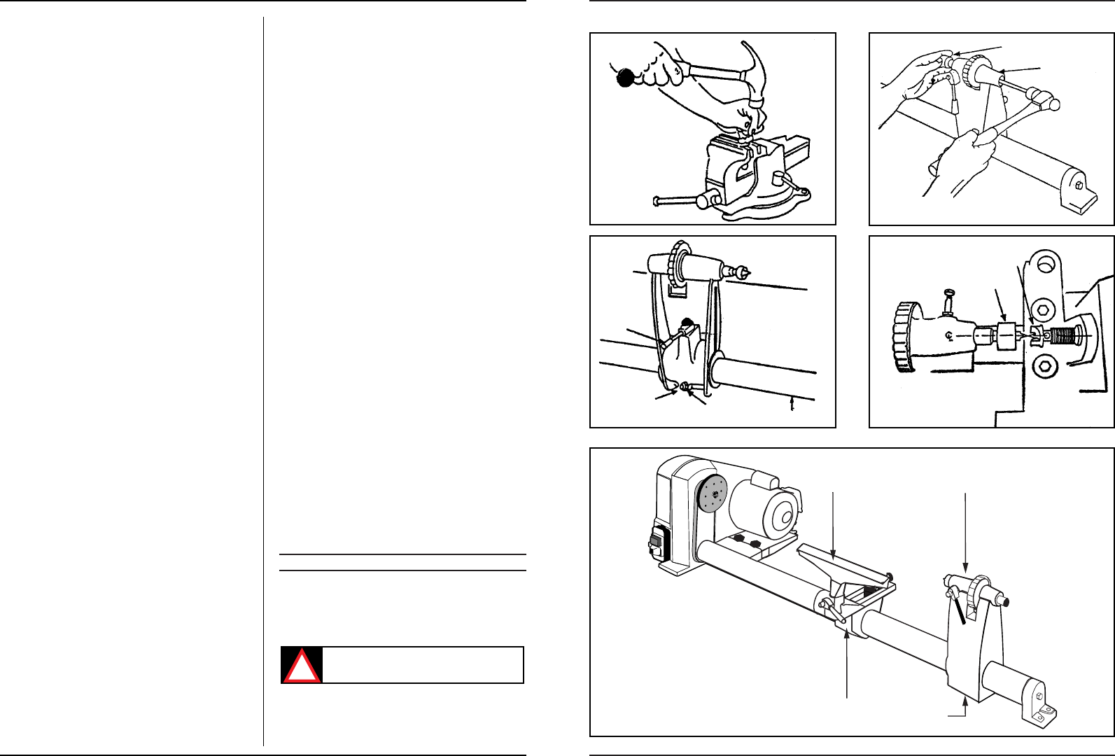
7. REMOVAL OF CUP CENTRE FROM RAM
To remove the cup centre from tail stock ram, insert
6 mm wood dowel or brass rod through the hole in the
tail stock ram. Hold the centre with one hand and tap do-
wel or rod with a hammer. (Fig.5).
8. ADJUSTING TAIL STOCK TO BED
The tail stock supports the workpiece for spindle tur-
ning. To prevent excessive looseness or rocking it con-
tains an adjustment-feature which bears against the key-
way on the underside of the bed. To adjust refer to (Fig. 6)
and proceed with the following:
With the tail stock loosened, tighten down the adjusting
screw moderately against the keyway, then loosen about
1/4 turn.
With the tail stock still loosened, slide the tailstock along
the full length of the bed. lf it binds or sticks in any one spot
loosen the adjusting screw only enough so that the tail
stock slides smoothly. lf the tail stock feels loose and can
be rocked slightly, tighten the screw only enough so that
it will not bind when sliding the full length of the bed,
When both conditions have been met, tighten the lock
nut.
9. ALIGNMENT OF TAIL STOCK CENTRE TO
HEAD STOCK CENTRE
The spur centre and the cup centre are used for spindle
turning and should always be in alignment. To align cent-
res refer to Fig. 7 and adjust as follows:
Slide the tail stock toward the head stock so that the two
points of the centres are very close but not touching.
Tighten the tail stock lock. Loosen the bolt in the foot
about two turns (do not drive the bolt forward with a
blow because this will loosen the connector clamp and
the alignment of the keyway will be lost). Using a 5 mm set
screw wrench loosen the set screw on the back of the
head stock which secures the bed. This screw is located
about 45 mm. up from the bench. Swing the tail stock so
that the two points are in line, then tighten the set screw
in the head stock and the bolt in the end of the foot,
10.INSTALLATION OF BRASS SLUGS ON
LOCKS
1. Brass slugs are required under the lock boLts of both
the tail stock (G) and the tool rest base (I). The purpo-
se of these brass slugs is to securely grip onto the bed
Who, locked down without scarring the bed.
2. Locate the two (2) brass slugs in the box of parts.
3. Remove the lock bolt in each assembly. Refer to Fig. 8
(D) ond (H) for locations.
4. lnsert a brass slug in the threaded hole of each lock
and then replace the lock bolts with wrench handles
attached.
11.ASSEMBLY OF THE CARRIER PLATE AND
THE SANDING ACCESSORY
Two carrier plates are supplied with the lathe, of which
one (marked with "IN") is used for clamping workpieces
in order to be able to rotate.
The other one (marked with "OUT") is attached to the
main axle, on the left side of the machine. This carrier pla-
te has a left thread and is used to clamp workpieces in or-
der to be able to sand by hand. For this purpose the pro-
tective lid must be removed.
5. BASIC LATHE OPERATIONS
1. LATHE PARTS, CONTROLS AND FUNC-
TIONS (Fig. 8)
Recome familar with the purpose of the various opera-
ting controls and parts of your lathe. Read and under-
stand this manual before attempting to use the lathe.
Make sure that the power cord is removed
from the supply before attempting to change
the belt position.
2. CHANGING SPEEDS
The belt is shown positioned on the second steps from
the outside end of the pulleys in Fig. 9. This causes the lat-
he to turn at 2.120 RPM. Refer to Fig. 10. Suppose you