554977
2
Zoom out
Zoom in
Vorherige Seite
1/4
Nächste Seite
CA-340 modular car alarm 2/4 VAV50204
Car alarm CA-340 “Nestor” installation
We recommend having the car alarm installed by an authorized service company.
Improper installation can result in damage to your vehicle. The car alarm
manufacturer shall not be held responsible for any damage caused by incorrect
installation or misuse of the product.
The immobilizer relay contact of car alarm is connected only in disarmed
mode and if the ignition is on. Do not block circuits that are under voltage
while the ignition is off. It could cause a serious damage of the vehicle.
The SIR output switches power supply. If is installation with 24V power
supply there must be used the siren type SA-606-24V or other type for 24V
instead of standard packaged siren.
First, disconnect the car battery. Nobody should be inside a vehicle equipped with
airbags during the manipulation of the battery (disconnecting, connecting). Keep in
mind that some devices equipped with a memory can be erased when the battery is
disconnected.
Attach the newly installed wires to the original bundles. When making connections
use a crimping tool fit for this purpose. If possible, avoid drilling into metal parts during
installation. If you have to drill any holes, make sure you avoid damaging any other
parts of the vehicle. The basic car alarm unit is suitable for installation in the
passenger compartment (the best position would be under the dashboard).
The car alarm functions can be set comfortably using the CA-340PRG wireless
programming module.
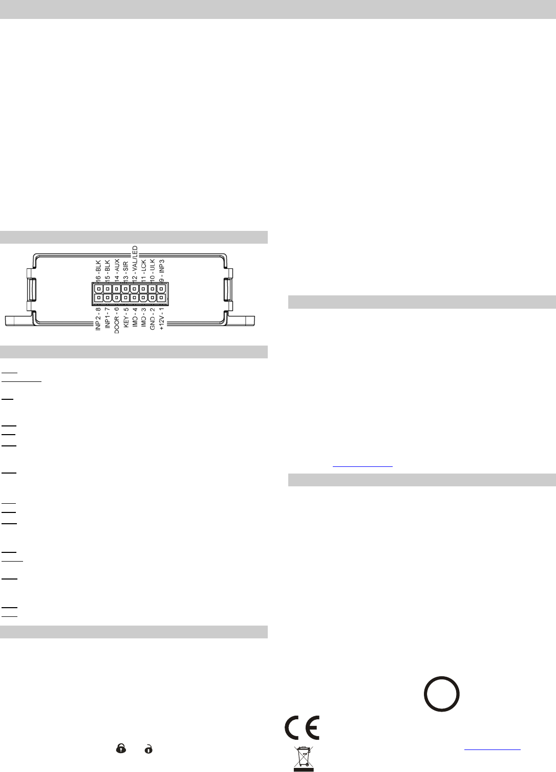
Car alarm connector description
Wire functions
GND black – connect to the negative pole of the power supply.
+12V / +24V red – connect to the positive pole of the power supply. Protected with a
built-in fuse.
SIR yellow – siren output, the maximum current is 1.5A.
If there is a short circuit or current overload, the output is disconnected. Reconnection
is possible only with another activation of the output.
BLK 2x violet – direction indicator relay or boot bounce control.
IMO 2x brown – immobilizer relay contact
ULK white and blue – central locking alarm input / output – unlocking signal. As an
input it reacts to the connection or disconnection of GND. If it has an output function, it
reacts to the connection of GND.
LCK black and white – central locking alarm input / output – locking signal. As an
input it reacts to the connection or disconnection of GND. If it has an output function, it
reacts to the connection of GND.
LED green – positive output of the LED.
VAL
green and black – connection of the Valet setting button
AUX pink – output providing power supply to auxiliary detectors (12V) or CR-11
module control output.
Its function is set with programming parameter 11 (see the table below).
KEY blue – ignition key input, alarm input. Reacts to +12/24V induction.
DOOR grey – door switch input, reacts to the connection to GND (it has optional
activation polarity if set for RC-8x remote control).
INP1 white – alarm input (reacts to the connection to GND) or direction indicator
signal input (reacts to the disconnection from GND). Its function is determined by the
connection and setting as mentioned below.
INP2 yellow and white – alarm input, optional activation polarity, optional reaction.
INP3 white and green – alarm input, reacts to the connection to GND.
Programmable functions
The car alarm offers optional function parameters (see the table) which can be set
in the programming mode. Entering the programming mode:
1. Press the Valet button and hold it for 4 – 6 s and then switch on the ignition key
Entering the programming mode is confirmed with two long chirps of the siren. The
alarm concurrently transmits its “enrolment code“.
2. It is then necessary to select between optional parameter setting and the
enrolment of wireless detectors. Press the Valet button to enter optional
parameter setting and then follow section 6. If you want to enter the wireless
device enrolment mode, switch off the ignition key (within 2 s). Then follow
Section 3.
3. Now you can enroll the RC-8x remote controls * (max. 4). The remote controls
can be enrolled by pressing both and keys simultaneously for approx. 3 s.
The enrolment is confirmed with a siren chirp. All remote controls can be erased
by switching off the ignition key for a short time. Press the Valet button to continue
to internal detector enrolment. Switching off the ignition key for more than 3 s
terminates the programming mode (the siren emits two short chirps).
4. Enrolment of detectors installed in the vehicle* (internal ones). This group
includes detectors guarding the interior of the vehicle (not if the alarm is armed
partially). If a remote control is enrolled in this group, it can be used to trigger a
PANIC alarm. Internal detectors can be erased by switching off the ignition key for
a short time. Press the Valet button to continue to external detector enrolment.
Switching off the ignition key for more than 3 s terminates the programming mode
(the siren emits two short chirps).
5. Enrolment of external detectors* (guarding of a garage). Detectors in this
group are active both during partial and complete arming. The JA-80A wireless
siren can also be enrolled here. External detectors can be erased by switching off
the ignition key for a short time. A maximum of 8 detectors can be enrolled. Press
the Valet button to continue to optional parameter setting pursuant to the following
article. Switching off the ignition key for more than 3s terminates the programming
mode (the siren emits two short chirps).
6. Now you can set the first parameter. The parameter setting is signaled with an
LED (on / off). Changes can be performed by switching off the ignition key for a
short time (no longer than 3 s).
7. Press the Valet button to go on to the next parameter. The number of siren chirps
indicates the parameter which you are currently setting. The tenth parameter is
signaled with a long siren chirp, while from the eleventh parameter onwards the
siren signals only parameter units (e.g. 11= 1 chirp, etc).
8. Switching off the ignition key for more than 3s terminates the programming mode
without saving (the siren emits two short chirps).
9. To save your settings you have to go through all 18 parameters. When the last
parameter has been set, press the Valet button once more. The termination of the
mode is confirmed with a long chirp of the siren.
* PLEASE NOTE! Enrolling the first device erases all previously enrolled devices in the
given group (you should therefore gradually enroll all devices which you want to use)
Wireless components of the OASIS system
It is possible to use motion detectors, glass break detectors and magnetic
detectors (JA-85P, JA-85B, JA-81M) to guard the vehicle interior or a garage. The
maximum of 8 detectors can be enrolled. A low battery in a detector is signaled
with its LED, the car alarm LED and also with a siren when the system is armed.
The CA-340SIR wireless siren with the bonnet contact input can be installed in
the engine compartment, so that it is not necessary to install the wires in the
vehicle interior.
The alarm can also be signaled via JA-80A and JA-80L internal wireless sirens.
(when using JA-80A you have to take into account that there is a delay depending
on the jumper setting in the siren)
The alarm can be enrolled to the OASIS electronic home security system as a
detector.
Wireless detectors have a tamper contact. Manipulation with detectors (when
changing batteries) is thus possible only if the ignition key is switched on and the
car alarm is unarmed. Otherwise alarm is triggered.
For more detailed information concerning wireless components for the guarding of
objects go to www.jablotron.com.
Technical specifications
Power supply voltage 12/24 V (9 – 32)V DC
Stand-by curent consumption 11 mA
TRX frequency switching range 1 RF channel 868,5 MHz
Transmitter power < 25 mW
Operational temperature range -40 to +85°C
SIR output +12V (24V), max. load 1.5 A
Alarm duration 30 s
Immobilizer circuit current 8 A cont., 12 A intermittent
BLK relay circuit current
PGM output current
8 A cont., 12 A intermittent
25 mA
ULK/LCK output current 200 mA
Enclosure (EN 60529) IP30
Dimensions 118 x 80 x 35 mm
Complies with:
ECE regulation No. 97.01
RTTE directive 1999/5/EC
Safety EN 60950-1
EMC ISO 7637, ISO 11452, CISPR-12
Radio interference ETSI EN 300 220
Can be operated according to ERC REC 70-03
JABLOTRON ALARMS Inc. hereby declares that the CA-340 is in compliance
with the essential requirements and other relevant provisions of ECE
Regulation No. 97.01, Directive 1999/5/EC and 1995/56/EC
The original of
the conformity assessment can be found at www.jablotron.com
, Technical
Support section
Note: Although this product does not contain any harmful materials we suggest you
return the product to the dealer or directly to the producer after use.
E
8 97 R A-01 5862
2

Brauchen Sie Hilfe? Stellen Sie Ihre Frage.

Forenregeln

Missbrauch melden von Frage und/oder Antwort

Libble nimmt den Missbrauch seiner Dienste sehr ernst. Wir setzen uns dafür ein, derartige Missbrauchsfälle gemäß den Gesetzen Ihres Heimatlandes zu behandeln. Wenn Sie eine Meldung übermitteln, überprüfen wir Ihre Informationen und ergreifen entsprechende Maßnahmen. Wir melden uns nur dann wieder bei Ihnen, wenn wir weitere Einzelheiten wissen müssen oder weitere Informationen für Sie haben.

Art des Missbrauchs:

Zum Beispiel antisemitische Inhalte, rassistische Inhalte oder Material, das zu einer Gewalttat führen könnte.

Beispielsweise eine Kreditkartennummer, persönliche Identifikationsnummer oder unveröffentlichte Privatadresse. Beachten Sie, dass E-Mail-Adressen und der vollständige Name nicht als private Informationen angesehen werden.

Forenregeln

Um zu sinnvolle Fragen zu kommen halten Sie sich bitte an folgende Spielregeln:

Neu registrieren

Registrieren auf E - Mails für Jablotron CA-340 Nestor wenn:


Sie erhalten eine E-Mail, um sich für eine oder beide Optionen anzumelden.


Das Handbuch wird per E-Mail gesendet. Überprüfen Sie ihre E-Mail.

Wenn Sie innerhalb von 15 Minuten keine E-Mail mit dem Handbuch erhalten haben, kann es sein, dass Sie eine falsche E-Mail-Adresse eingegeben haben oder dass Ihr ISP eine maximale Größe eingestellt hat, um E-Mails zu erhalten, die kleiner als die Größe des Handbuchs sind.

Ihre Frage wurde zu diesem Forum hinzugefügt

Möchten Sie eine E-Mail erhalten, wenn neue Antworten und Fragen veröffentlicht werden? Geben Sie bitte Ihre Email-Adresse ein.


Info