JK-15 PROFI GSM KIT 2/4 MGK22902
4. Detectors and accessories installation
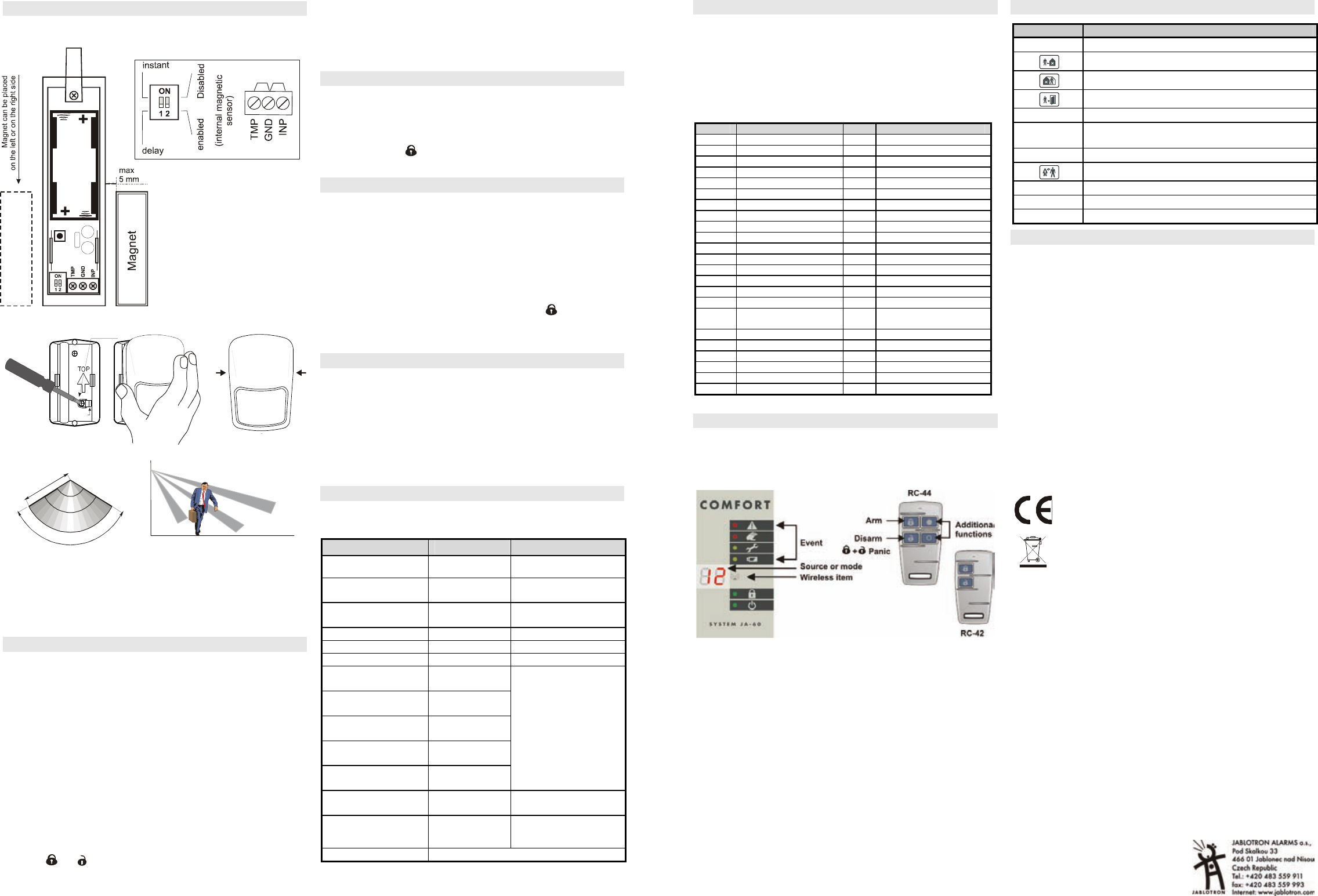
a) Install JA-60N magnetic de (antenna
pointing up or down)
b) Install JA-60P motion PIR det
A
attach
C
open
B
click
rear tamper
lever
Don't ov
this s
2
2,5
1,5
1
0,5
1,6 3,7
12
range
[m]
height
[m]
120
ş
1
2
m
zone A
zone B
zone C
zone A
zone B
zone C
JA-60P cover
Avoid lo
Select Instant via the DIP switch
the detectors.
c) Connect the detector batt(pull out the red tape to
activate the batteries)
d) Attach the keypad to the desired location
e) Plug the UC-260 wireless into a power socket.
5. Enrollment of additional accessories
If you install additional detectors (max. 32), you have
them. The syP m(if not enter F0 606
a) Press 1 to enter the learning mode*
b) The next free detector position will be displaye
keypad.
c) Install batteries into all new detectors step by step to enr
them (system will automatically offer the next free position)
d) To scpress
(down)
e) Tsecond detector to an
before you install the detector
f) To exit the learning mode press the N key
The w(JA-60F) enrolls after yo
while in the learning mode.
The remote contro (RC-4x) enro
both the
and buttons while in the learnin
The wireless outdoo (JA-60A) enrolls after it is powered
up while in the learning mode
To enroll t enter 29 on the
keypad while in the P mode
Check the manuals of individual items for more details
*Learning mode
in the control panel.
6. Detector and controller testing
a) The system should be in P mode (if not, enter F0 6060)
b) Trigger the – their addresses (1=door and 2=PIR)
should be displayed (if the PIR detector does not react, re-
enter its test mode by opening and closing its cover)
c) Press button
on the RC-4x remote contro– c2 will be
indicated on the alarm display
7. Radio signal strength measurement
a) While P mode, press 1 and then using 7 scroll to position 1
b) Press 8 to start measuring
c) Act the door detector to view its signal strength
d) Using 1 key, scroll to the next p (2=PIR) and
check its signal strength (if the PIR detector does not react,
re-enter its test mode by opening and closing its cover)
e) Repeat step d) to check all enrolled items. The wireless keypad
(c1) signal is indicated afteremote
control (c2) is indica
.
f) Change the location of an item if its signal is lower than 2
g) Return to P mode by pressing the N key
8. GSM communication testing
a) Call back the system number using your mobile. Let the SMS
phone ring until the system answ
beep). Then enter the installer remote access code 0000 on
your mobile.
b) Now mobile should work as a system keypad. Press the
# ∗ 0 6060
c) End the phone call
d) From y
system. You shstatus report reply
9. Programming the system
a) The system should be in P mode (if no
b) Using the following sequences
Function Sequence
Comments
Your installer code* 5 xxxx xxxx
6060 = factory default
xxxx = new code
Installer remote
access code*
94 xxxx F0
0000 = factory default
xxxx = customized code
User remote access
code*
94 xxxx F1
1111 = factory default
xxxx = new code
Exit delay
20x
3=30sec factory def.
Entrance delay
21x
3=30 sec factory def.
Alarm duration
22x
4=4min factory def.
Alarm SMS reporting
71 yyy..y F0
72 yyy..y F0
Alarm SMS + phone
call reporting
73 yyy..y F0
74 yyy..y F0
Alarm & arming SMS
reporting
75 yyy..y F0
76 yyy..y F0
Alarm phone call
only
77 yyy..y F0
Technical trouble
SMS reporting
78 yyy..y F0
yyy..y = phone number
7n F0 erases number n
User 1 to 4 armi
reporting to 75
80x
x=1 enabled
x=2 disabled
GSMLink
pre-registration
972 yyy..yF0
yyy..y = your mobile
number (international
format 00 country …)
Time & date entry
4 hh mm DD MM YY
See control panel installation manu
* Must be changed
JK-15 PROFI GSM KIT 3/4 MGK2
10. SMS text editing
Factory default SMS texts in
Jablotron’s Comlink softw
yyyy∗ TXT ∗ z,text,z,text,z,text.....
yyyy = installer remote access code (0000 = factory default)
∗ = separator, space can also be used
z = text index, see the following table
text = new text (no commas or periods/full stops allowed)
z Factory z Fac
700 Alarm system report 415 Wireless detec
201 Controller 416 Wireless det
202 Controll 501 U
203 Controll 502 U
204 Controll 503 U
205 Controll 504 U
206 Controll 505 U
207 Controll 506 U
208 Controll 507 U
401 Wireles 508 User code #
402 Wireles 509 User code #
403 Wireless 510 User code #10
404 Wireless 511 User code #11
405 Wireless 512 User code #12
406 Wireless 513 User code #13
407 Wireless 514 User code #14
408 Wireless det
z Factory default
commands
409 Wireless det 703 AM
410 Wireless det 704 DM
411 Wireless det 705 MO
412 Wireless det 706 ME
413 Wireless det 710 PGON
414 Wireless det 711 PGOFF
A complete list of all texts is in the control panel installation manual
11. Finishing the installation
a) Fill in the information on
the keypad cover.
b) Switch the system to standby (by pressing the N key)
c) Instruct the user on how to operate the system
12. Keypad operation
13. Specifications
Power 230 VAC, max 0.1 A, supervised, class II
Backup battery 12 V, 2.26 Ah, normal life time 5 years
Backup power output 13VDC, the max. permanent current is 0.4
or 1A for max. 15 min (1 cycle per hour),
Self consumption of the control panel is 30 mA; JA-60E 25 mA
Hard-wired inputs 4 input zones, selectable triggering:
Wireless zones 16 zones (2 detectors can be enrolled to each
Wireless controllers max. 8 (JA-60F, RC-22, RC-44)
Access codes master code and 14 user codes.
Wired outputs Alarm relay dry contacts 1A/60V;
Programmable outputs PgX , Pg
Siren output 12 V, 0.7 A
Events memory 127 most recent events
Working frequency*433.92 MHz; digital hopping code; supervised communication
Comply with EN 50131-1, EN 50131-6
Securi 2 (low t
Environmental class II indoor – general (-10 to 40oC)
Safety EN 60950, class II
EMC ETS
Radio characteristics ETSI EN 300220
Can be operated according to ERC REC 70-03
Jablotron Alarms as that the JA-63 Profi con
panel is in compliance with the esse
relevant provision
conformity assessment can be
www.jablotron.com, Technical Support section.
Note: Dispose of batteries
batteries and local
any harmful mate
dealer or directl
Entry Function
user code
Arming / Disarming
F1 /
Arming without code
F2 /
Partial arming
F3 /
Door lock opening
F4
Memory reading
F5
New master code (example: F5 1234 2789
2789)
F6 User code setting (example: F6 1234 03 3344 )
F7 /
Disarming under duress
F8
Appliance control (F81 = ON, F80 = OF
F0 M.code
User test mode (example F0 1234)
N
Escape & fault detail reading