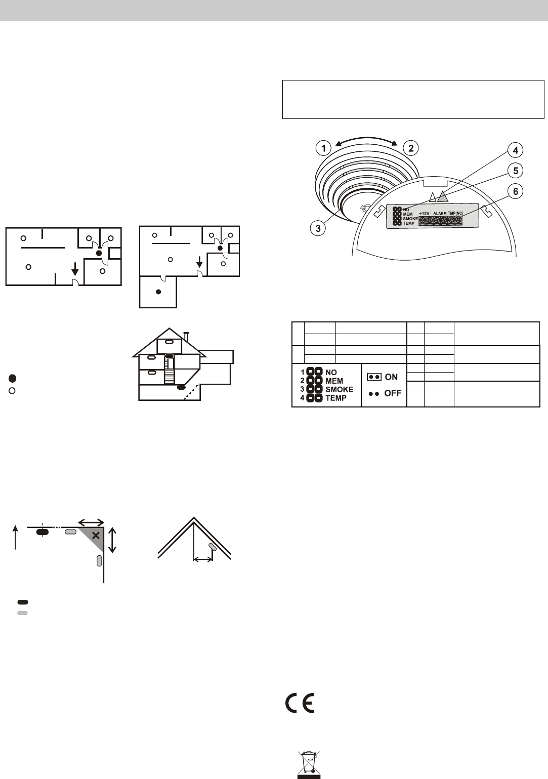
status signalling; 4 – arrow showing where to insert the detector; 5 –
configuration jumpers; 6 – connection terminals;
1. open the detector cover, by turning it anti-clockwise
2. attach the removed plastic base to the desired place with screws (not shown above).
3. set the required detector function – see the table below
ON NO contact 3 OFF
1
OFF NC contact 4 OFF
smoke (EN 54-7) or
heat (EN 54-5)
ON memory ON 3 ON
2
OFF memory OFF 4 OFF
smoke only (EN 54-7)
(not heat)
3 OFF
4 ON
heat only (EN 54-5)
(not smoke)
3 ON
4 ON
Both smoke and heat
(both conditions at the
same time)
4. connect ALARM and TMP terminals – first study the control panel installation manual
before connecting wires to the detector terminal board
TMP- has only NC function
5. connect power supply to the 12V terminals
6. close the module cover. The detector can be inserted in the plastic base in one position
only. The correct position is marked with arrows on both plastic parts.
Fire alarm
Optical detector: When smoke penetrates into the detector, the detector starts
flashing red.
Heat detector: When the temperature reaches the set limits, the detector starts
flashing red.
Alarm memory: If it is enabled, alarm indication continues even when the smoke clears
or when the temperature decreases. The indication is terminated by disconnecting power
supply or by turning the detector anti-clockwise (tamper sensor activation).
Fault indication
The detector checks its functioning. If any faults are discovered, it starts flashing
rapidly for about 2 minutes. Then there are 3 short flashes every 30 seconds.
In such a case, disconnect the power supply for 1 minute and then reconnect it. If the
LED indicator starts flashing again after 1 minute, send the detector to a service centre.
Technical specifications
Power 9 - 15V DC / 5 mA
Smoke detection optical light scattering
Smoke detector sensitivity m = 0.11 - 0.13 dB/m pursuant toEN 54-7
Heat detection class A2 according to EN 54-5
Alarm temperature + 60°C to + 70°C
Operating temperature range -10 to +80°C
Dimensions, weight diameter 126 mm, height 52 mm, 150 g
Conformity EN 54-7, EN 54-5, EN 50130-4, EN 55022
1923-CPD-0244
JABLOTRON ALARMS a.s. hereby declares that the SD-282ST detector is in
compliance with the essential requirements and other relevant provisions of
Directive 1989/106/EC and 2004/108/EC. The original of the conformity
assessment can be found at www.jablotron.com, Technical Support section.
Note: Although this product does not contain any harmful
materials we suggest you return the product to the dealer or
directly to the producer after use. For more information visit
www.jablotron.com.
Brauchen Sie Hilfe? Stellen Sie Ihre Frage.
Missbrauch melden von Frage und/oder Antwort
Libble nimmt den Missbrauch seiner Dienste sehr ernst. Wir setzen uns dafür ein, derartige Missbrauchsfälle gemäß den Gesetzen Ihres Heimatlandes zu behandeln. Wenn Sie eine Meldung übermitteln, überprüfen wir Ihre Informationen und ergreifen entsprechende Maßnahmen. Wir melden uns nur dann wieder bei Ihnen, wenn wir weitere Einzelheiten wissen müssen oder weitere Informationen für Sie haben.
Art des Missbrauchs:
Forenregeln
Um zu sinnvolle Fragen zu kommen halten Sie sich bitte an folgende Spielregeln:
Lesen Sie zuerst die Anleitung;
Schauen Sie nach, ob die Frage bereits gestellt wurde;
Stellen Sie die Frage so deutlich wie nur einigermaßen möglich;
Erwähnen Sie was Sie bereits versucht haben um das Problem zu lösen;
Ist Ihr Problem von einem Besucher gelöst dann lassen Sie ihn / sie wissen in diesem Forum;
Falls Sie reagieren möchten, so verwenden Sie bitte das Antworten- Formular;
Da ihre Frage für alle Besucher sichtbar ist, sollten Sie lieber keine persönliche Daten erwähnen.
Neu registrieren
Registrieren auf E - Mails für Jablotron SD-282ST wenn:
neue Frage gestellt werden
neue Handbücher vorhanden sind
Sie erhalten eine E-Mail, um sich für eine oder beide Optionen anzumelden.
Das Handbuch wird per E-Mail gesendet. Überprüfen Sie ihre E-Mail.
Wenn Sie innerhalb von 15 Minuten keine E-Mail mit dem Handbuch erhalten haben, kann es sein, dass Sie eine falsche E-Mail-Adresse eingegeben haben oder dass Ihr ISP eine maximale Größe eingestellt hat, um E-Mails zu erhalten, die kleiner als die Größe des Handbuchs sind.
Ihre Frage wurde zu diesem Forum hinzugefügt
Möchten Sie eine E-Mail erhalten, wenn neue Antworten und Fragen veröffentlicht werden? Geben Sie bitte Ihre Email-Adresse ein.