window. If you are using an aftermarket source
unit, with conventional preamp-level outputs, this
is most likely the position that you will use.
The “High” position on the “Input Voltage”
switch selects an input sensitivity range between
800mV and 8V. This is useful for certain high-
output preamp level signals as well as speaker-level
output from source units and small amplifiers.To
use speaker-level sources, splice the speaker output
wires of the source unit or small amplifier onto a
pair of RCA cables or plugs.
The output of the amplifier will decrease for a
given input voltage when the “Input Range” switch
is placed in the “High” position. Conversely, the
output will be higher with the switch in the “Low”
position.While this may sound counter-intuitive, it is
consistent with the descriptions above.
3) Input Sensitivity Adjustment: Located next to
the “Input Voltage” switch, in the “Amplifier Input
Section”, is a rotary control labeled “Input Sens.”.
Once the appropriate “Input Voltage” range has
been selected, this rotary control can be used to
match the source unit's output voltage to the input
stage of the amplifier for maximum clean output.
Rotating the control clockwise will result in higher
sensitivity (louder for a given input voltage).
Rotating the control counter-clockwise will result in
lower sensitivity (quieter for a given input voltage).
To properly set the amplifier for maximum clean
output, please refer to Appendix B (page 14) in this
manual. After using this procedure, you can then
adjust the level of the amplifier by adjusting the
input sensitivity downward, if the amplifier requires
attenuation to achieve the desired system balance.
Do not increase the “Input Sens.” setting for
any amplifier in the system beyond the maximum
level established during the procedure outlined
in Appendix B (page 14). Doing so will result in
audible distortion and possible speaker damage.
CROSSOVER CONTROLS
Crossovers are groups of individual electronic filters
which allow only certain frequency ranges to pass
through them by attenuating frequencies outside
the selected range.These filters allow the user to
specify what frequency range will be sent out of
each channel section of the amplifier.This, in turn,
allows each speaker system to only reproduce a
range of frequencies it is well-suited for, resulting in
reduced distortion and improved fidelity.
AMPLIFIER LOW-PASS FILTER
The 1000/1 employs a sophisticated, state-variable,
low-pass active filter for its internal channel.This
feature is designed to attenuate frequencies above its
filter frequency, so that the system's subwoofers do
not reproduce any audible midrange content.
1) Filter Operation: The low-pass filter in the
1000/1 is fully variable between 40 Hz and 200 Hz
via the “Filter Freq.” control knob and features the
ability to select between a moderate “12dB” per
octave or a steep “24dB” per octave slope via the
“Mode/Slope” switch.
Depending on the subwoofer system and the
vehicle, different slopes may be required to produce
a smooth transition to the mid-bass speakers in the
system. Experiment to find the slope which best
matches the acoustic requirements of your system.
Hint: A trunk mounted sub whose output has to
"fight" through a rear deck or a back seat often
benefits from the 12 dB/octave slope which lets
more upper bass content pass through. A sub that
fires directly into the listening environment is more
likely to benefit from a 24 dB/octave slope.
JL AUDIO 1000/1 7
REMOTE TURN-ON
The 1000/1 uses a conventional +12V remote
turn-on lead, typically controlled by the source unit's
remote turn-on output.The amplifier will turn on
when +12V is present at its “Remote” input and
turn off when +12V is switched off. If a source unit
does not have a dedicated remote turn-on output,
the amplifier’s turn-on lead can be connected to
+12V via a switch that derives power from an
ignition-switched circuit.
The 1000/1's “Remote” turn-on connector is
designed to accept 12 AWG – 8 AWG wire.
12 AWG is more than adequate for this purpose.
To connect the remote turn-on wire to the
amplifier, first back out the set screw on the top of
the amplifier, using the supplied hex wrench. Strip
1/2 inch (12mm) of wire and insert the bare wire
into the receptacle on the front panel of the
amplifier, seating it firmly so that no bare wire is
exposed. Smaller wire than 12 AWG can be used,
but it may be necessary to strip 1 inch of insulation
from the wire and fold the bare wire in half prior to
insertion.While holding the wire in the terminal,
tighten the set screw firmly, taking care not to strip
the head of the screw and making sure that the
wire is firmly gripped by the set screw.
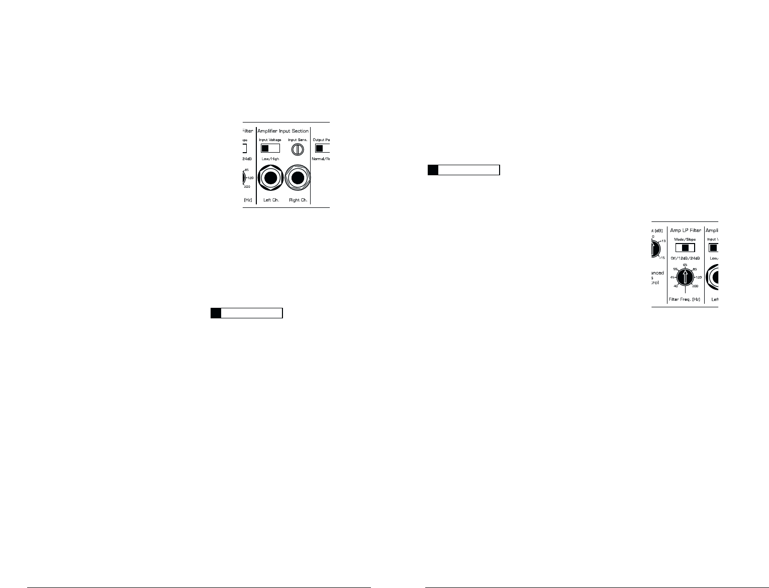
AMPLIFIER INPUT SECTION
The 1000/1 employs a differential-balanced
input topology that provides the user with a high
degree of input flexibility while retaining superior
noise rejection.This type of circuit also allows the
1000/1 to accept high-voltage inputs from factory
source unit outputs without excessive distortion
or noise problems.
1) Input Connections: A standard left/right
pair of RCA type jacks is used for input on
the 1000/1.You may run a stereo or a mono
signal into the inputs of the amplifier.The
amplifier's input section automatically sums
stereo signals to mono for the internal amplifier
section and for the “LP” “Filter Mode” of the
“Preamp Output” section.
If you plan to use the “Preamp Output” of the
1000/1 to feed a stereo amplifier, you must connect
a stereo signal to the input of the amplifier. A mono
signal into the amplifier will result in a mono signal
out of the preamp output. (It's a great amplifier, but
it doesn't do magic).
The amplifier will operate with only one input
connection (left or right), but will require an
increase in input sensitivity to overcome the loss
of signal. If a mono input signal is to be run, we
recommend that you use a “Y-adaptor” to split the
mono signal into both inputs of the amplifier.
2) Input Voltage Range: A wide range of signal
input voltages can be accommodated by the
1000/1's input section (200mV – 8V).This wide
range is split up into two sub-ranges, accessible via
switches located in the “Amplifier Input Section”
of the amplifier.
The “Low” position on the “Input Voltage”
switch selects an input sensitivity range between
200mV and 2V. This means that the “Input Sens.”
rotary control will operate within that voltage