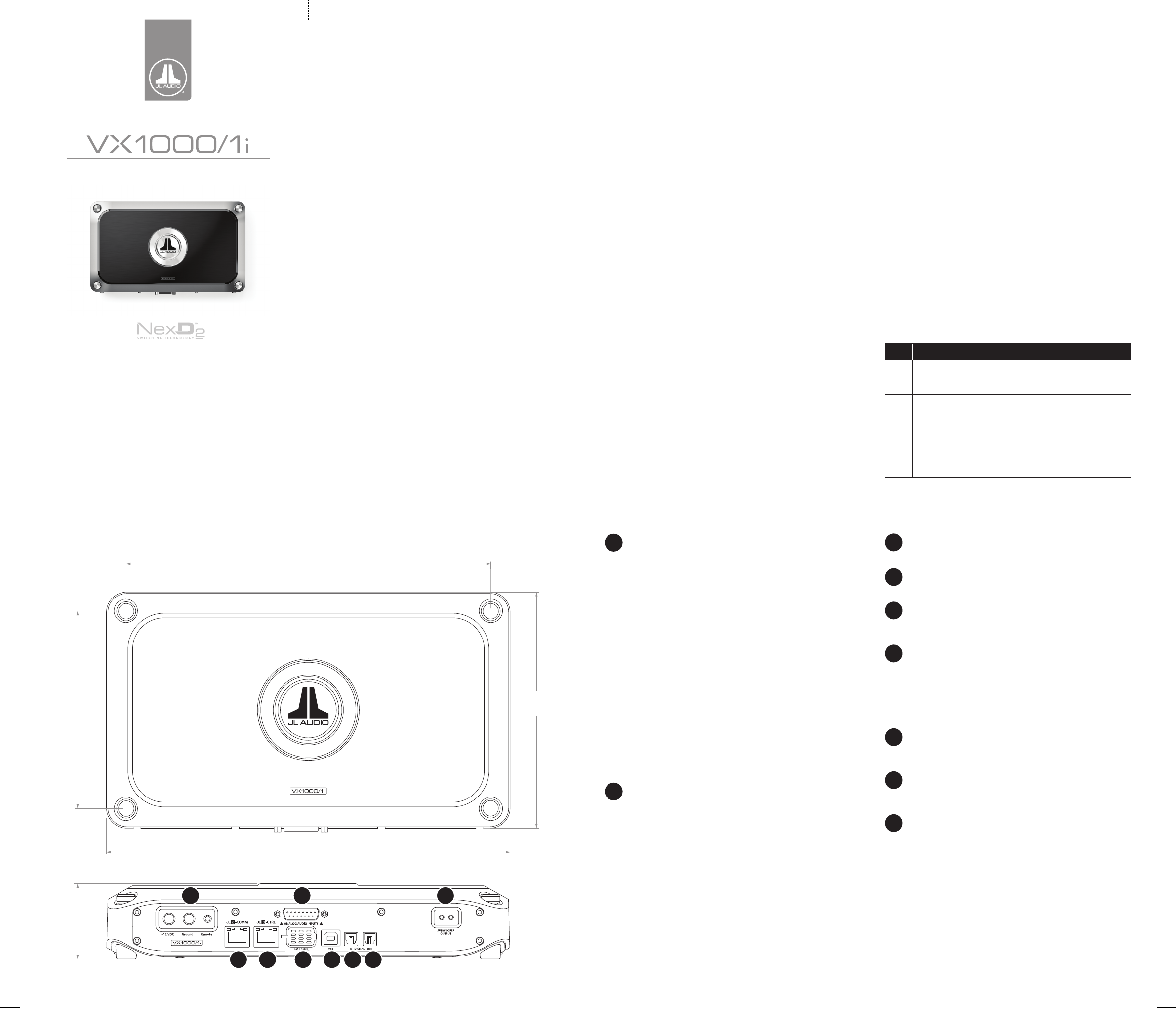
Thank you for purchasing a JL Audio amplifier for your sound system. Your amplifier has been designed and manufactured to exacting standards in order to ensure years of musical enjoyment. For maximum performance, we highly recommend that you have your new amplifier installed by an authorized JL Audio dealer. Your authorized dealer has the training, expertise and installation equipment to ensure optimum performance from this product. Should you decide to install the amplifier yourself, please take the time to read this manual thoroughly to familiarize yourself with its installation requirements and setup procedures. If you have any questions regarding the instructions in this manual or any aspect of your amplifier’s operation, please contact your authorized JL Audio dealer for assistance. If you need further assistance, please contact the JL Audio Technical Support Department at technical@jlaudio.com or call (954) 443–1100 during business hours.
1000W Monoblock Class D Subwoofer Amplifier with Integrated DSP
Installation Applications This amplifier is designed for operation with 12 volt, negativeground electrical systems. Using this product in systems with positive ground and/or voltages other than 12V may result in damage to the product and will void the warranty. This product is not certified or approved for use in aircraft. Product Description This is a monoblock, Class D subwoofer amplifier equipped with the second generation of JL Audio’s NexD2™ high-speed switching technology. It is engineered to deliver reference-grade audio amplification with outstanding efficiency and unprecedented, built-in processing power. Instead of traditional analog processing controlled by knobs and switches, VXi amplifiers feature an integrated DSP (Digital Signal Processor). The amplifier and its integrated DSP are configured using an external device (PC, Tablet or Phone), with the appropriate JL Audio TüN™ application installed. (See What is TüN? section for more info.)
with
Planning Your Installation It is important that you take the time to read this manual thoroughly and that you plan your installation carefully. It is very easy to damage expensive vehicle systems in modern automobiles. Never assume that you have found appropriate wires without consulting a reliable wiring diagram or without analyzing with proper test equipment. If you are uncomfortable or unfamiliar with reading diagrams or testing methods, please enlist the services of your authorized JL Audio dealer to perform the installation. Your authorized dealer has the training, expertise and installation equipment to ensure optimum performance from this product. The following are some considerations that you must take into account when planning your installation.
CONNECTION GUIDE
Safety Considerations • Install your amplifier in a dry, well-ventilated location that does not interfere with your vehicle’s safety equipment (air bags, seat belt systems, ABS brake systems, etc.). • Do not mount the amplifier in the engine compartment or in any areas of extreme heat. • Securely mount the amplifier so that it does not come loose in the event of a collision/sudden jolt or as a result of repeated vibrations during normal operation. • Check before drilling to make sure that you will not be drilling into a fuel tank, gas/brake line, wiring harness, or other vital system. • Do not run system wiring outside or underneath the vehicle/vessel. This is an extremely dangerous practice, which can result in severe damage/injury. • Take the necessary precautions when making connections to the vehicle’s battery. • Protect all system wires from sharp edges by carefully routing them, tying them down and using grommets and loom where appropriate. • Secure all wiring as needed, using cable ties or wire clamps to protect them from moving parts and sharp edges. Cooling Efficiency Considerations The outer shell of your JL Audio amplifier is designed to remove heat from the amplifier circuitry. For optimum cooling performance, this outer shell should be exposed to as large a volume of air as possible. Enclosing the amplifier in a small, poorly ventilated chamber can lead to excessive heat build-up and degraded performance. If an installation calls for an enclosure around the amplifier, we recommend that this enclosure be ventilated with the aid of a fan. In normal applications, fan-cooling is not necessary. If mounting the amplifier under a seat, make sure there is at least 1 inch (2.5 cm) of space above the amplifier’s outer shell to permit proper cooling.
(1) Amplifier (1) Analog Input/Pre-Out Harness (1) JL Audio Badge (1) USB A/B Cable (6 ft./1.8 m) (2) Black Hex Cap Machine Screws (2) Silver Thumbscrews (1) Connection Guide
(1) Power Connector (1) Subwoofer Output Connector (4) Corner Caps (1) Corner Cap Tool (1) 2.5 mm Hex Wrench (1) 3 mm Hex Wrench
JL Audio Badge To complement the amplifier’s mounting orientation, the logo badge includes a recessed key feature allowing it to be affixed at 90 degree increments on the amplifier’s top. To install, remove the adhesive backing and press the badge at the desired orientation.
Power Connector
T he VX1000/1i’s “+12 VDC” and “Ground” connections are designed to accept up to 2 AWG copper wire. Note: Copper Clad Aluminum (CCA) wire is not recommended. 4 AWG is the minimum copper wire size for this amplifier. A. B.
6.62 in 168 mm
5.53 in 141 mm
C.
D.
2
Run copper wire from the positive (+12V) battery post to the amplifier mounting location. If additional amplifiers are being installed, run the appropriate gauge copper wire for the combined, maximum current draw, and install a fused distribution block near the amplifiers. An appropriate fuse (sold separately) at the main power wire(s) is vital for vehicle safety. This fuse must be installed within 18 inches (45 cm) of the battery post connection. If this is the only device connected to this main wire, use a 80 A fuse. Do not install the fuse until the power wire has been securely connected to the amplifier. The ground connection should be made to a clean, solid metal grounding point using copper wire, and kept as short as possible. The metal surface of the grounding point should be sanded to create a clean, metal-to-metal connection. For optimal grounding, we recommend using a JL Audio ECS master ground lug (XB-MGLU). All ground connections (source unit and amplifiers) should be made at the same location. The remote connection should be made to the source unit’s positive (+12V) remote turn-on output. If your source unit does not have a dedicated remote turn-on output, consider one of the alternative turn-on options. (See Turn-On Mode section for more info.)
Analog Input/Pre-Out Harness
The Analog Input Harness accepts the following connections: Line-Level Analog Inputs: Two female RCA jacks feed a differentialbalanced input section, providing a high degree of input flexibility, and retaining superior noise rejection. This type of input architecture also allows the VX1000/1i to cleanly accept any analog audio signal up to 16 VRMS, without using a line-output converter.
11.32 in 287 mm
1
2
3
2.12 in 54 mm
4
5
6
7
8
9
Making Connections VXi amplifiers utilize removable plugs and harnesses to make the following connections: • Power Connector and Subwoofer Output Connector To connect the power, ground, remote turn-on and subwoofer output wires to the amplifier, back out the set screws on each connector using the supplied hex wrenches. Strip back 3/8 inch (10 mm) of insulation from the end of each wire and insert the bare wire into the receptacle on the power connector plug, seating it firmly so that no bare wire is exposed. While holding each wire in place, tighten each set screw firmly, taking care not to strip the head of the screw. Install each connector by plugging it into the amplifier’s corresponding receptacle, pushing firmly. •A nalog Input/Pre-Out Harness This harness includes connections for Signal Input (RCA plugs), Preamp Outputs (RCA plugs), Remote Turn-On Output (wire lead) and Valet Input (wire lead). Select either the included black hex cap machine screws or the silver thumbscrews to secure the Analog Input Harness connector to the amplifier. Turn-On Mode VXi amplifiers can be switched on and off using one of three methods, configured by the “Turn On Mode” setting in the TüN™ Software Interface. Refer to the table below for detailed info and decide which option is best suited for your specific system. Setting
Mode
Remote
Conventional (Preferred)
DC Offset
DC Offset Sensing (Auto)
Signal
Signal Sensing (Auto)
Function
What is Included
1 10.22 in 260 mm
Corner Cap Installation and Removal The corner caps are designed to conceal the amplifier’s mounting holes and hardware. To install, simply press a corner cap into each mounting hole. To avoid scratching the amplifier’s chassis during removal, use the included, plastic corner cap tool and lift below each cap.
Preamp Outputs: Two female, RCA jacks deliver line-level, analog audio outputs (Max 4 V RMS) that are compatible with most types of aftermarket equipment. These are configured with the TüN™ Software Interface. Remote: This connection provides a positive (+12V) turn-on voltage (475 mA limit) to activate other aftermarket equipment (similar to an aftermarket head unit’s remote turn-on lead). Valet: When connected to negative ground, this connection activates the Valet Mode Preset and will remain active until the ground connection is removed. This preset is configured using the TüN™ Software Interface and will override any DRC controlled preset.
3
Turn-on/off controlled by your source unit. Automatically turns on by detecting the presence of small DC signal in OEM audio outputs and turns off (within 5 minutes) after the signal is removed. Automatically turns on by detecting full-range OEM audio signals and turns off (within 5 minutes) after the signal is removed (varies, depending on input signal levels).
Connection Connect your source unit’s +12V remote turn-on output to the Power Connector’s Remote Turn-On Input connection.
This circuit senses the Analog Input 1 only. Note: The sensitivity of this circuit is designed for high-level (speaker level) signals, not for low-level (preamp level) signals. Make sure the OEM audio outputs contain midrange signals.
Subwoofer Output Connector
Connect the subwoofer wires to the corresponding terminals.
4
JLid-COMM
Connect optional accessories (VXi-BTC, VXi-HUB, etc.) to this port.
5
JLid-CTRL
Connect optional DRC (Digital Remote Controller) wired controllers to this port.
6
SD + Reset
Lift the dust cover to access the following utility functions: Reset Buttons: Use a small pin to perform the following: Reboot Amp - Press and release the right button. Factory Reset (wipe memory, reboot amp) - Press and hold the left button for 7 seconds. Micro SD Slot: For service/future expansion.
7
USB
This USB A/B port permits connection to a computer for configuration and tuning, using the TüN™ Software.
8
DIGITAL-In
Toslink port accepts 2-channel digital audio signal from any optical (S/PDIF) digital output, with a sample rate up to 192 kHz.
9
DIGITAL-Out
Provides a digital audio output (24 bit/96 kHz) that is not susceptible to RF interference or noise-generating electrical conditions. By default, this is a pass-through audio output, with no signal processing applied, and intended for use with other equipment that have an optical (Toslink) digital audio input (S/PDIF) port. Using the TüN™ Software Interface, you may configure this output’s routing, equalization, output level and DRC control functionality.
LED Status/Condition Reporting LEDs located on the chassis top and connection panel are used to communicate amplifier status and condition. Refer to the table below for the location and meaning for each behavior.
Wiring Diagram - VX1000/1i
LED / Location LED Ring / Amplifier Top
Upper Left LED / JLid-COMM Port and JLid-CTRL Port
+ SUB –
Behavior
Critical Voltage
Flashing Red
Critical Temperature
Flashing Yellow
Excessive Current
Green
Detecting JLid™ Device
Blue
JLid™ Connection Success
Yellow
Invalid JLid™ Device
Flashing Red
+12 VDC - Positive (+12V) Battery Connection
SUB - To Subwoofer(s): (+ and –)
Ground - Negative (–) Ground Connection
Status/Condition›
Flashing Blue
Upper Right LED / JLid-COMM Port
Flashing Red
Upper Right LED / JLid-CTRL Port
Green
Excessive Current Critical Voltage/Temperature Excessive Remote Output Current Active TüN™ Connection
Remote - Positive (+12V) Turn-On Input From Source Unit JLid-COMM - Optional Network Hub or Bluetooth® Communicator Connection (Sold Separately)
USB A/B Cable To Computer with TüN™ software installed
Input 2 - Ch. 2 Input Input 1 - Ch. 1 Input Pre-Out Right - Analog Preamp Output Pre-Out Left - Analog Preamp Output
Included Not Included
Remote - Turn-On Output (+12V) Valet - Valet Preset Toggle (–)
Specifications
Connections Power Connector
Amplifier Specifications
Connection
Wire Capacity
+12 VDC (+)
2 AWG
Positive (+12V) Power Connection to Battery
Ground (–)
2 AWG
Negative (GND) Chassis Ground Connection
Remote
18 to 10 AWG
Description
Positive (+12V) Remote Turn-On Input from Source Unit Analog Input Harness
Label
Plug/Wire Color
Input 1
White RCA
Channel 1 Signal Input
Input 2
Red RCA
Channel 2 Signal Input
Power Supply Type
Unregulated MOSFET Switching
Operating Voltage
10 - 15V DC
Recommended Fuse
Input Voltage Range
White RCA
Preamp Signal Output 1
Red RCA
Preamp Signal Output 2
Remote
Blue
Valet
Green
Positive (+12V) Turn-On Output (475 mA limit)
Connection
Wire Capacity
SUB +
14 to 10 AWG
(+) Positive Subwoofer Output
Description
SUB –
14 to 10 AWG
(–) Negative Subwoofer Output
Label
Type
JLid-COMM
RJ45 Jack
Data Connections
1000W x 1 @2Ω
Rated RMS Power @ 12.5V, <1% THD+N
500W x 1 @4Ω
650W x 1 @3Ω
800W x 1 @2Ω
Frequency Response
12 Hz - 500 Hz (+0, -1dB)
S/N Ratio, (A-weighted, 20 kHz noise bandwidth)
87 dB (Referred to rated power), 60 dB (Referred to 1 W)
S/N Ratio, (A-weighted, 20 kHz noise bandwidth)
87 dB (Referred to rated power), 56 dB (Referred to 1 W)
What is TüN? TüN™ is software that you use to configure, tune and control your VXi amplifier, and other JL Audio DSP products. TüN™ automatically recognizes what it is connected to, and allows you to make adjustments with a clear interface specifically set up for that product. TüN™ is available for download for free in a variety of applications, for computers and most handheld devices. For more information, visit: jlaudio.com/tun
4 AWG
Analog Inputs
Negative (GND) Ground Input (activates the Valet Mode Preset) Subwoofer Output Connector
Micro SD Slot
2nd-Gen NexD™ High Speed Class D
Standby Current Draw
Pre-Out Left
Reset Buttons
Amplifier Topology
Min. Copper Power/GND Wire
Description
Pre-Out Right
SD + Reset
DIGITAL-Out To Optical Digital (S/PDIF) Input on Next Device
Standard CAT5 Network Cables
Digital Input
ANALOG INPUTS / PRE-OUTS
JLid-CTRL - Optional Digital Remote Controller (DRC) Connection (Sold Separately)
DIGITAL-In - From Optical Digital (S/PDIF) Source
Optical Audio Cables
Bit Depth/Sample Rate
Used for future expansion
Type
Type
Type
AKM AK7738, processing at 24 bit/96 kHz
For Windows® PC or Mac® computers, TüN™ connects via USB and offers complete control and command of the entire VXi feature set from the comfort of your desk or driver’s seat. Software also runs in demo mode, without connected amplifiers, for offline setup or demo purposes. Test drive it for free!
For iPad or Android tablets. Enjoy the full-featured TüN™ software experience on your tablet, with the freedom of a wireless connection via Bluetooth®. Requires VXi-BTC Bluetooth® Communicator.
Line-Level, Differential-Balanced 2, via harness-mounted female RCA jacks S/PDIF Optical via chassis-mounted Toslink port Up to 24 bit/192 kHz 2 Line-Level, via harness-mounted female RCA jacks 4 V RMS S/PDIF Optical via chassis-mounted Toslink port
Wireless connection and streamlined options, for fast and simple amplifier setup. Download TüN™ Express for iPhone, iPad and Android phones & tablets. Requires VXi-BTC Bluetooth® Communicator.
Limited Warranty – Amplifiers (USA) JL Audio warrants this product to be free of defects in materials and workmanship for a period of two (2) years from the original date of purchase. This warranty is not transferable and applies only to the original purchaser from an authorized JL Audio dealer. Should service be necessary under this warranty for any reason due to manufacturing defect or malfunction, JL Audio will (at its discretion), repair or replace the defective product with new or remanufactured product at no charge. Damage caused by the following is not covered under warranty: accident, misuse, abuse, product modification or neglect, failure to follow installation instructions, unauthorized repair attempts, misrepresentations by the seller. This warranty does not cover incidental or consequential damages and does not cover the cost of removing or reinstalling the unit(s). Cosmetic damage due to accident or normal wear and tear is not covered under warranty. Warranty is void if the product’s serial number has been removed or defaced. Any applicable implied warranties are limited in duration to the period of the express warranty as provided herein beginning with the date of the original purchase at retail, and no warranties, whether express or implied, shall apply to this product thereafter. Some states do not allow limitations on implied warranties, therefore these exclusions may not apply to you. This warranty gives you specific legal rights, and you may also have other rights, which vary from state to state. If you need service on your JL AUDIO product: All warranty returns should be sent to JL Audio ’s Amplifier Service Facility freight-prepaid through an authorized JL Audio dealer and must be accompanied by proof of purchase (a copy of the original sales receipt). Direct returns from consumers or non-authorized dealers will be refused unless specifically authorized by JL Audio with a valid return authorization number. Warranty expiration on products returned without proof of purchase will be determined from the manufacturing date code. Coverage may be invalidated as this date is previous to purchase date. Non-defective items received will be returned freight-collect. Customer is responsible for shipping charges and insurance in sending the product to JL Audio. Freight damage on returns is not covered under warranty.
For Service Information in the U.S.A. please call JL Audio Customer Service: (954) 443-1100 9:00 AM – 5:30 PM (Eastern Time Zone) JL Audio, Inc. 10369 North Commerce Pkwy. Miramar, FL 33025 (Do not send product for repair to this address) International Warranties: Products purchased outside the United States of America are covered only by that country’s distributor and not by JL Audio, Inc.
24 bit/96 kHz
Dimensions LxWxH
11.32 in x 6.62 in x 2.12 in / 287 mm x 168 mm x 54 mm
VX1000/1i_MAN_041118
Missbrauch melden von Frage und/oder Antwort
Libble nimmt den Missbrauch seiner Dienste sehr ernst. Wir setzen uns dafür ein, derartige Missbrauchsfälle gemäß den Gesetzen Ihres Heimatlandes zu behandeln. Wenn Sie eine Meldung übermitteln, überprüfen wir Ihre Informationen und ergreifen entsprechende Maßnahmen. Wir melden uns nur dann wieder bei Ihnen, wenn wir weitere Einzelheiten wissen müssen oder weitere Informationen für Sie haben.
Art des Missbrauchs:
Forenregeln
Um zu sinnvolle Fragen zu kommen halten Sie sich bitte an folgende Spielregeln:
Lesen Sie zuerst die Anleitung;
Schauen Sie nach, ob die Frage bereits gestellt wurde;
Stellen Sie die Frage so deutlich wie nur einigermaßen möglich;
Erwähnen Sie was Sie bereits versucht haben um das Problem zu lösen;
Ist Ihr Problem von einem Besucher gelöst dann lassen Sie ihn / sie wissen in diesem Forum;
Falls Sie reagieren möchten, so verwenden Sie bitte das Antworten- Formular;
Da ihre Frage für alle Besucher sichtbar ist, sollten Sie lieber keine persönliche Daten erwähnen.
Neu registrieren
Registrieren auf E - Mails für JL Audio 1i wenn:
neue Frage gestellt werden
neue Handbücher vorhanden sind
Sie erhalten eine E-Mail, um sich für eine oder beide Optionen anzumelden.
Holen Sie sich Ihr Benutzerhandbuch per E-Mail
Geben Sie Ihre E-Mail-Adresse ein, um das Handbuch zu erhalten von JL Audio 1i in der Sprache / Sprachen: Englisch als Anhang in Ihrer E-Mail.
Das Handbuch ist 0,3 mb groß.
Sie erhalten das Handbuch in Ihrer E-Mail innerhalb von Minuten. Wenn Sie keine E-Mail erhalten haben, haben Sie wahrscheinlich die falsche E-Mail-Adresse eingegeben oder Ihre Mailbox ist zu voll. Darüber hinaus kann es sein, dass Ihr ISP eine maximale Größe für E-Mails empfangen kann.
Das Handbuch wird per E-Mail gesendet. Überprüfen Sie ihre E-Mail.
Wenn Sie innerhalb von 15 Minuten keine E-Mail mit dem Handbuch erhalten haben, kann es sein, dass Sie eine falsche E-Mail-Adresse eingegeben haben oder dass Ihr ISP eine maximale Größe eingestellt hat, um E-Mails zu erhalten, die kleiner als die Größe des Handbuchs sind.
Ihre Frage wurde zu diesem Forum hinzugefügt
Möchten Sie eine E-Mail erhalten, wenn neue Antworten und Fragen veröffentlicht werden? Geben Sie bitte Ihre Email-Adresse ein.