6 | JL Audio - 300/4v3 Owner
7
on eaI” switc
input s
Th
leve
f
spe
w
onto a pa
or us
adaptor (X
IMPORT
The out
for a gi
Ra
posit
w
t
as descri
3) : Loc
to tInput V” s
seI
Sens.”. Once tInput V”
ra
us
to t
cha
t
sen
Rota
resu
input vo
of a
out
in t
you ca
cha
dow
t
syI
Sens.” s
be
t
1
a
botInput S ” adjust
be ma
a
a
for f
a
CROSSO
Cros
f
ra
f
f
ra
of t
spe
f
reduc
Fron
Bridged
Left Right
+12VDC Ground Remote
Front F
Front Input Section Front Speaker Outputs
Bridged
Left Right
Rear Speaker Outputs
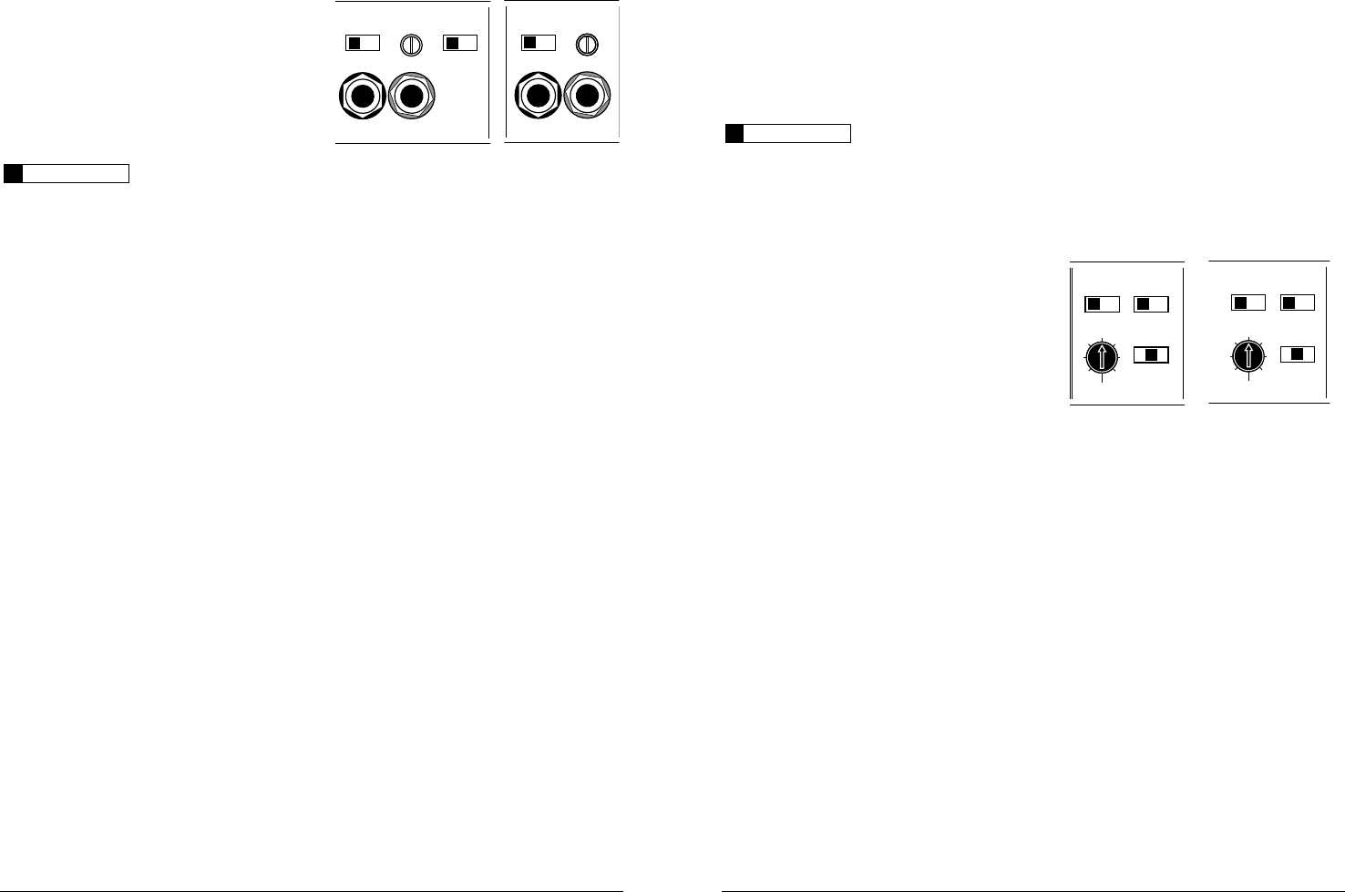
Left Ch. Right Ch.
Filter Fr
Filter Slope
Freq. Range
Input Voltage Input Sens. Input Mode
12dB
|
24dB
Filter Mode
Off
|
LP
|
HP
x1
|
x10
Low
|
High
Rear Input Section
Left Ch. Right Ch.
Input Voltage Input Sens.
Low
|
High 2ch
|
4ch
50
60
75
95
1
200
500
30 0 /v3
Four-Channel Full-Range Amplifier
Rear Filter Contr
Filter Fr
Filter Slope
12dB
|
24dB
Filter Mode
Off
|
LP
|
HP
x1
|
x10
50
60
75
95
1
200
500
Bridged
Left Right
+12VDC Ground Remote Front F Front Input Section Front Speaker Outputs
Bridged
Left Right
Rear Speaker Outputs
Left Ch. Right Ch.
Filter Slope
Freq. Range
Input Voltage Input Sens. Input Mode
12dB
|
24dB
Filter Mode
Off
|
LP
|
HP
x1
|
x10 Low
|
High
Rear Input Section
Left Ch. Right Ch.
Input Voltage Input Sens.
Low
|
High 2ch
|
4ch
50
60
75
95
1
200
500
30 0 /v3
Four-Channel Full-Range Amplifier
Rear Filter Contr
Filter Fr
Filter Slope
12dB
|
24dB
Filter Mode
Off
|
LP
|
HP
x1
|
x10
50
60
75
95
1
200
500
Th
ident
cha
fol
1) Fi ”
to con
t
“Off ”
se
f
pa
ut
ra
“LP ” (L
at
f
subwo
“HP ” (Hi
att
f
of compon
se
Ground Connection
Th
usi
kep
piec
t
poi
bet
t
ri
t
lug (XB
sc
IMPORT
Ma
A
cha
con
dr
A
sy
TU
Th
tu
un
tuRemote ”
input a
a sou
tu
be con
power f
ThRemote ”
des
12 A
T
a
of t
St
ba
of t
w
be ne
t
in
t
st
t
FR
Th
one for its f
cha
tInput V” s
aInput S ” rota
Bridged
Left Right
+12VDC Ground Remote Front F
Front Input Section
Front Speaker Outputs
Bridged
Left Right
Rear Speaker Outputs
Left Ch. Right Ch.
Filter Fr
Filter Slope
Freq. Range
Input Voltage Input Sens. Input Mode
12dB
|
24dB
Filter Mode
Off
|
LP
|
HP
x1
|
x10
Low
|
High
Rear Input Section
Left Ch. Right Ch.
Input Voltage Input Sens.
Low
|
High
2ch
|
4ch
50
60
75
95
1
200
500
30 0 /v3
Four-Channel Full-Range Amplifier
Rear Filter Contr
Filter Fr
Filter Slope
12dB
|
24dB
Filter Mode
Off
|
LP
|
HP
x1
|
x10
50
60
75
95
1
200
500
Bridged
Left Right
+12VDC Ground Remote Front F Front Input Section Front Speaker Outputs
Bridged
Left Right
Rear Speaker Outputs
Left Ch. Right Ch.
Filter Slope
Freq. Range
Input Voltage Input Sens. Input Mode
12dB
|
24dB
Filter Mode
Off
|
LP
|
HP
x1
|
x10 Low
|
High
Rear Input Section
Left Ch. Right Ch.
Input Voltage Input Sens.
Low
|
High
2ch
|
4ch
50
60
75
95
1
200
500
30 0 /v3
Four-Channel Full-Range Amplifier
Rear Filter Contr
Filter Fr
Filter Slope
12dB
|
24dB
Filter Mode
Off
|
LP
|
HP
x1
|
x10
50
60
75
95
1
200
500
ThFront Input S ” a
“Input Mod ” sw
four a
input s
1 If you w
a
pair o2ch ” posit
on tI ” s
si
in Front I ”
t
to t
If you w
a
rea
is e
“4” on t Input Mo”
mode
ca
2) A w
input vo
of t
Th
ra
input s
eacInput V” s
w
ma
aL ” I
Vo” s
ra
tI .
w
a
prea
posHigh ”