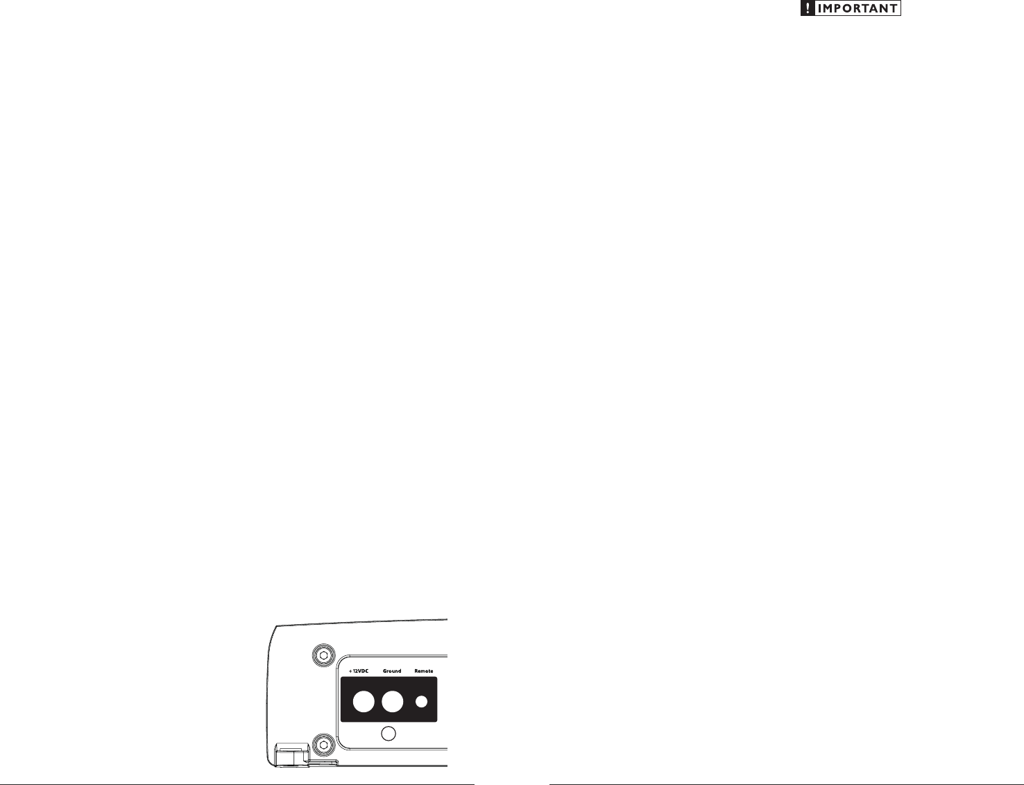
701304
3
Zoom out
Zoom in
Vorherige Seite
1/11
Nächste Seite
The A4300’s “+12VDC” and “Ground
connections are designed to accept 8 AWG -
4 AWG power wire. 8 AWG is a minimum power
wire size for this amplifier.
If you are installing the A4300 with other
amplifiers and wish to use a single main power
wire, use 4 AWG or larger main power wire
(depending on the overall current demands of all
the amplifiers in the system). This 4 AWG or
larger power wire should terminate into a
distribution block mounted as close to the
amplifiers as possible and should connect to the
A4300 with 8 AWG - 4 AWG power wire.
Note: Smaller AWG numbers mean bigger wire
and vice-versa (1/0 AWG is the largest, 2 AWG is
smaller, then 4 AWG, then 8 AWG, etc.).
To connect the power wires to the amplifier,
first back out the set screw on the top of the
terminal block, using the supplied 2.5 mm hex
wrench. Strip 1/2 inch (12 mm) of insulation from
the end of each wire and insert the bare wire into
the terminal block, seating it firmly so that no
bare wire is exposed. While holding the wire in
place, tighten the set screw firmly, taking care not
to strip the head of the screw.
The ground connection should be made using
the same gauge wire as the power connection
and should be kept as short as possible, while
accessing a solid piece of sheet metal in the
vehicle. The surface of the sheet metal should
be sanded at the contact point to create a clean,
metal-to-metal connection between the chassis
and the termination of the ground wire. For
optimal grounding, we recommend the use of a
JL Audio ECS master ground lug (XA-MGL-1).
Alternatively, a sheet metal screw or bolt can be
used with a star washer.
Any wires run through metal barriers (such
as firewalls), must be protected with a high
quality rubber grommet to prevent damage to the
insulation of the wire. Failure to do so may result
in a dangerous short circuit.
Many vehicles employ small (10 AWG -
6 AWG) wire to ground the battery to the
vehicle chassis and to connect the alternators
positive connection to the battery. To prevent
voltage drops, these wires should be upgraded
to 4 AWG when installing amplifier systems
with main fuse ratings above 60A.
FUSE REQUIREMENTS
It is absolutely vital that the main power
wire(s) to the amplifier(s) in the system be
fused within 18 inches (45 cm) of the positive
battery post connection. The fuse value at each
power wire should be high enough for all of the
equipment being run from that power wire. If
only the A4300 is being run from that power wire,
we recommend a 40A fuse be used. AFS (mini
blade fuse), AGU (big glass fuse) or MaxiFuse™
(big plastic-body fuse) types are recommended.
No fuse is required or recommended directly
before the amplifier power connection. If one is
desired, we recommend the use of a 40A fuse.
TURNON LEAD
The A4300 uses a conventional +12V remote
turn-on lead, typically controlled by the source
units remote turn-on output. The amplifier will
turn on when +12V is present at itsRemote
input and turn off when +12V is switched off. If
a source unit does not have a dedicated remote
turn-on output, the amplifiers turn-on lead can
be connected to +12V via a switch that derives
power from an ignition-switched circuit.
The A4300’s Remote turn-on connector is
designed to accept 18 AWG – 12 AWG wire. To
connect the remote turn-on wire to the amplifier,
first back out the set screw on the top of the
terminal block, using the supplied 2.5mm hex
wrench. Strip 1/2 inch (12mm) of wire and insert
the bare wire into the terminal block, seating it
firmly so that no bare wire is exposed. While
holding the wire in the terminal, tighten the set
screw firmly, taking care not to strip the head of
the screw and making sure that the wire (not the
insulation) is firmly gripped by the set screw.
JL AUDIO A4300 5
PRODUCT DESCRIPTION
The JL Audio A4300 is a four-channel,
full-range audio amplifier utilizing patented
Absolute Symmetry™ Class A/B technology
for all channels.
The A4300 can be operated with a wide variety
of source units and system configurations.
TYPICAL INSTALLATION SEQUENCE
The following represents the sequence
for a typical amplifier installation, using an
aftermarket source unit or OEM Interface
processor (like the CleanSweep CL441dsp).
Additional steps and different procedures may
be required in some applications. If you have
any questions, please contact your authorized
JL Audio dealer for assistance.
1) Disconnect the negative battery post
connection and secure the disconnected cable
to prevent accidental re-connection during
installation. This step is not optional.
2) Run power wire (minimum 8 AWG) from the
battery location to the amplifier mounting
location, taking care to route it in such a
way that it will not be damaged and will not
interfere with vehicle operation. Use 4 AWG
or larger power wire and a power distribution
block if additional amplifiers are being
installed with the A4300.
3) Connect power wire to the positive battery
post. Fuse the wire with an appropriate fuse
block (and connectors) within 18 inches (45
cm) wire length of the positive battery post.
This fuse is essential to protect the vehicle.
Do not install the fuse until the power wire
has been securely connected to the amplifier.
4) Run signal cables and remote turn-on wire
from the source unit to the final amplifier
mounting location.
5) Run speaker cables from the speaker systems
to the amplifier mounting location.
6) Find a good, solid metal grounding point
close to the amplifier and connect the
negative power wire to it using appropriate
hardware (use of the JL Audio ECS master
ground lug, XA-MGL-1 is recommended).
Use the same size power wire as the wire
connected to the “+12VDC” connection
(minimum 8 AWG), no longer than 36 inches
(90 cm) from the amplifier to the ground
connection point. In some vehicles, it may be
necessary to upgrade the battery ground wire.
(See page 5 for important notice).
7) Securely mount the amplifier using the
supplied screws.
8) Connect the positive and negative power
wires to the amplifier. A fuse near the
amplifier is not necessary.
9) Connect the remote turn-on wire
to the amplifier.
10) Connect the input cables to the amplifier.
11) Connect the speaker cables to the amplifier.
12) Carefully review the amplifier’s control
settings to make sure that they are set
according to the needs of the system.
13) Install the power wire fuse (40A for a
single A4300) and reconnect the negative
battery post terminal.
14) Turn on the source unit at a low level
to double-check that the amplifier is
configured correctly. Resist the temptation
to crank it up until you have verified the
control settings.
15) Make necessary adjustments to the input
sensitivity controls to obtain the right
overall output and the desired balance
in the system. See Appendix A (page 14)
for the recommended input sensitivity
setting method.
16) Enjoy the fruits of your labor with your
favorite music.
POWER CONNECTIONS
Before installing the amplifier, disconnect the
negative (ground) wire from the vehicle’s battery.
This will prevent accidental damage to the system,
the vehicle and your body during installation.
4 JL AUDIO A4300
3

Brauchen Sie Hilfe? Stellen Sie Ihre Frage.

Forenregeln

Missbrauch melden von Frage und/oder Antwort

Libble nimmt den Missbrauch seiner Dienste sehr ernst. Wir setzen uns dafür ein, derartige Missbrauchsfälle gemäß den Gesetzen Ihres Heimatlandes zu behandeln. Wenn Sie eine Meldung übermitteln, überprüfen wir Ihre Informationen und ergreifen entsprechende Maßnahmen. Wir melden uns nur dann wieder bei Ihnen, wenn wir weitere Einzelheiten wissen müssen oder weitere Informationen für Sie haben.

Art des Missbrauchs:

Zum Beispiel antisemitische Inhalte, rassistische Inhalte oder Material, das zu einer Gewalttat führen könnte.

Beispielsweise eine Kreditkartennummer, persönliche Identifikationsnummer oder unveröffentlichte Privatadresse. Beachten Sie, dass E-Mail-Adressen und der vollständige Name nicht als private Informationen angesehen werden.

Forenregeln

Um zu sinnvolle Fragen zu kommen halten Sie sich bitte an folgende Spielregeln:

Neu registrieren

Registrieren auf E - Mails für JL Audio A4300 wenn:


Sie erhalten eine E-Mail, um sich für eine oder beide Optionen anzumelden.


Das Handbuch wird per E-Mail gesendet. Überprüfen Sie ihre E-Mail.

Wenn Sie innerhalb von 15 Minuten keine E-Mail mit dem Handbuch erhalten haben, kann es sein, dass Sie eine falsche E-Mail-Adresse eingegeben haben oder dass Ihr ISP eine maximale Größe eingestellt hat, um E-Mails zu erhalten, die kleiner als die Größe des Handbuchs sind.

Ihre Frage wurde zu diesem Forum hinzugefügt

Möchten Sie eine E-Mail erhalten, wenn neue Antworten und Fragen veröffentlicht werden? Geben Sie bitte Ihre Email-Adresse ein.


Info