700479
2
Zoom out
Zoom in
Vorherige Seite
1/2
Nächste Seite
Limited Warranty – Amplifiers (USA)
JL Audio warrants this product to be free of defects in materials and
workmanship for a period of two (2) years from the original date of purchase.
This warranty is not transferrable and applies only to the original purchaser
from an authorized JL Audio dealer. Should service be necessary under this
warranty for any reason due to manufacturing defect or malfunction, JL
Audio will (at its discretion), repair or replace the defective product with new
or remanufactured product at no charge. Damage caused by the following is
not covered under warranty: accident, misuse, abuse, product modification or
neglect, failure to follow installation instructions, unauthorized repair attempts,
misrepresentations by the seller. This warranty does not cover incidental or
consequential damages and does not cover the cost of removing or reinstalling
the unit(s). Cosmetic damage due to accident or normal wear and tear is not
covered under warranty.
Warranty is void if the product’s serial number has been removed or defaced.
Any applicable implied warranties are limited in duration to the period of the
express warranty as provided herein beginning with the date of the original
purchase at retail, and no warranties, whether express or implied, shall apply
to this product thereafter. Some states do not allow limitations on implied
warranties, therefore these exclusions may not apply to you. This warranty gives
you specific legal rights, and you may also have other rights, which vary from
state to state.
If you need service on your JL AUDIO product:
All warranty returns should be sent to JL Audio ’s Amplifier Service Facility
freight-prepaid through an authorized JL Audio dealer and must be
accompanied by proof of purchase (a copy of the original sales receipt). Direct
returns from consumers or non-authorized dealers will be refused unless
specifically authorized by JL Audio with a valid return authorization number.
Warranty expiration on products returned without proof of purchase will be
determined from the manufacturing date code. Coverage may be invalidated
as this date is previous to purchase date. Non-defective items received will
be returned freight-collect. Customer is responsible for shipping charges and
insurance in sending the product to JL Audio. Freight damage on returns is not
covered under warranty.
For Service Information in the U.S.A. please call
JL Audio Customer Service:
(954) 4 43 -110 0
9:00 AM – 5:30 PM (Eastern Time Zone)
JL Audio, Inc.
10369 North Commerce Pkwy.
Miramar, FL 33025
(Do not send product for repair to this address)
International Warranties:
Products purchased outside the United States of America are covered only
by that country’s distributor and not by JL Audio, Inc.
Appendix A:
Input Sensitivity Level Setting
Following the directions below will allow the installer to adjust the input
sensitivity of each amplifier channel pair in just a few minutes using equipment
commonly available in installation bays.
Necessary Equipment
• Digital AC Voltmeter
• CD or file with a sine-wave test tone recorded at 0 dB reference level in the
frequency range to be amplified for that set of channels (50 Hz for subwoofer
channels, 1 kHz for a midrange application). Do not use attenuated test tones
(-10 dB, -20 dB, etc.).
The Nine-Step Procedure
1) Disconnect the speakers from the amplifier’s speaker output
connectors (you need only disconnect one speaker wire).
2) Turn off all processing (bass/treble, loudness, EQ, etc.) on the source
unit, processors (if used) and amplifier. Set the source unit’s fader
control to center position and its subwoofer level control to
3/4 of maximum.
3) Turn the “Input Sens. control all the way down.
4) Set the source unit volume to 3/4 of full volume. This will allow for
reasonable gain overlap with moderate clipping at full volume.
5) Using the chart on this page, determine the target voltage for input
sensitivity adjustment according to the nominal impedance of the
speaker system connected to the amplifier outputs.
6) Verify that you have disconnected the speakers before proceeding. Play
a track with an appropriate sine wave (within the frequency range to
be amplified) at 3/4 source unit volume.
7) Connect the AC voltmeter to the speaker output connectors of the
amplifier. Make sure you test the voltage at the correct connectors
(+ and –).
8) Increase the “Input Sens. control until the target voltage is observed
with the voltmeter.
9) Once you have adjusted the amplifier to its maximum low-distortion
output level, reconnect the speaker(s) and listen to the system. The
“Input Sens. controls can now be adjusted downward if the amplifier
requires attenuation to achieve the desired system balance.
Specications MX500/1
Rated RMS Power @
14.4V, <1% THD+N
300W x 1 @ 4 Ω 400W x 1 @ 3 Ω 500W x 1 @ 2 Ω
Rated RMS Power @
12.5V, <1% THD+N
250W x 1 @ 4 Ω 300W x 1 @ 3 Ω 400W x 1 @ 2 Ω
Frequency Response 20 Hz - 12 kHz (+0, -1dB), 7 Hz - 14 kHz (+0, -3dB)
S/N Ratio, A-weighted,
20 kHz noise bandwidth
97 dB (Referred to rated power), 70 dB (Referred to 1 W)
Damping Factor >115 / 50 Hz @ 4 Ω, >54 / 50 Hz @ 2 Ω
Input Voltage Range 250 mV - 4 V (Low) or 580 mV - 14 V (High)
Filter Modes Low-Pass, defeatable
Filter Freq. Range, Slope 40 - 400 Hz, 24 dB/Octave
Detented Filter Freq.
Potentiometers
40, 80, 130, 300 Hz (Calibrated)
Infrasonic Filter 20 - 40 Hz, 12 dB/Octave
Bass Boost EQ 0 to +12 dB @ 43 Hz
Output Polarity 0 or 180 degrees
Remote Bass Controller M-RBC-1 (sold separately)
Min Power/GND Wire 4 AWG
Fuse Rating 50 A
Dimensions 9.33 in x 4.50 in x 1.77 in / 237 mm x 114.5 mm x 45 mm
Appendix B
Remote Level Control
With the optional RBC-1 or M-RBC-1 Remote Level Control (each sold separately),
you can control the subwoofer volume from the front of the vehicle/vessel.
The remotes plug connects to the amplifiers harness-mounted RJ11 input
jack. When connected to the amplifier, the Remote Level Control operates as
follows. At full counter-clockwise rotation, the audio will mute completely. At full
clockwise rotation the level will be the same as if the remote was not connected
at all. In other words, it operates strictly as a level attenuator. This control will
not affect the “Bass Boost feature of the amplifier. Care should be taken to
securely mount this control in a manner that does not interfere with vehicle/
vessel operation. When setting the amplifiers input sensitivity, the Remote Level
Control should be unplugged or at full clockwise rotation (maximum level).
Problem Possible Cause Solution
How to properly set
input sensitivity
Please refer to Appendix A to set the
input sensitivity for maximum, low-
distortion output.
Amplifier doesn’t
turn on
Faulty fuse
Remove fuse and check with continuity
meter. Replace if necessary.
Poor connection
integrity
Check “+12V”, “Ground”, and “Remote”
leads for pinched wires; ensure tight
connections.
Insufficient
“Remote” input
Make sure there is a sufficient +12V
supply at the “Remote” connection; if
not a relay may be required.
Intermittent output,
fluctuates when I tap
on it or hit a bump
Poor connection
integrity
Make sure insulation has been properly
stripped back at connection points for
good contact area.
Make sure input connectors are making
good contact with input jacks of the
amplifier.
Distorted, attenuated,
or popping sound
Faulty speaker
connection (Short
Circuit / Over
Current Protection)
Inspect speaker wires for possible short-
circuit, either together or shorted to the
vehicles chassis ground.
Check the nominal load impedance at
the amplifier is equal to or greater than
2 ohms.
Output shuts off after
a while
Overheating
condition (Thermal
Protection)
Make sure amplifier mounting area has
adequate space for ventilation and heat
dissipation.
Troubleshooting
MX500/1
Nom. Impedance Target AC Voltage
34.6 V
34.6 V
31.6 V
Important!
Do not increase any “Input Sens. setting for any amplifier channel or
channel pair in the system beyond the maximum level established during
this procedure. Doing so will result in audible distortion and possible
speaker damage.
It will be necessary to re-adjust the “Input Sens.” for the affected channels if any
equalizer boost is activated after setting the “Input Sens.” with this procedure. This
applies to any EQ boost circuit, including source unit tone controls or EQ circuits. EQ
cuts will not require re-adjustment.
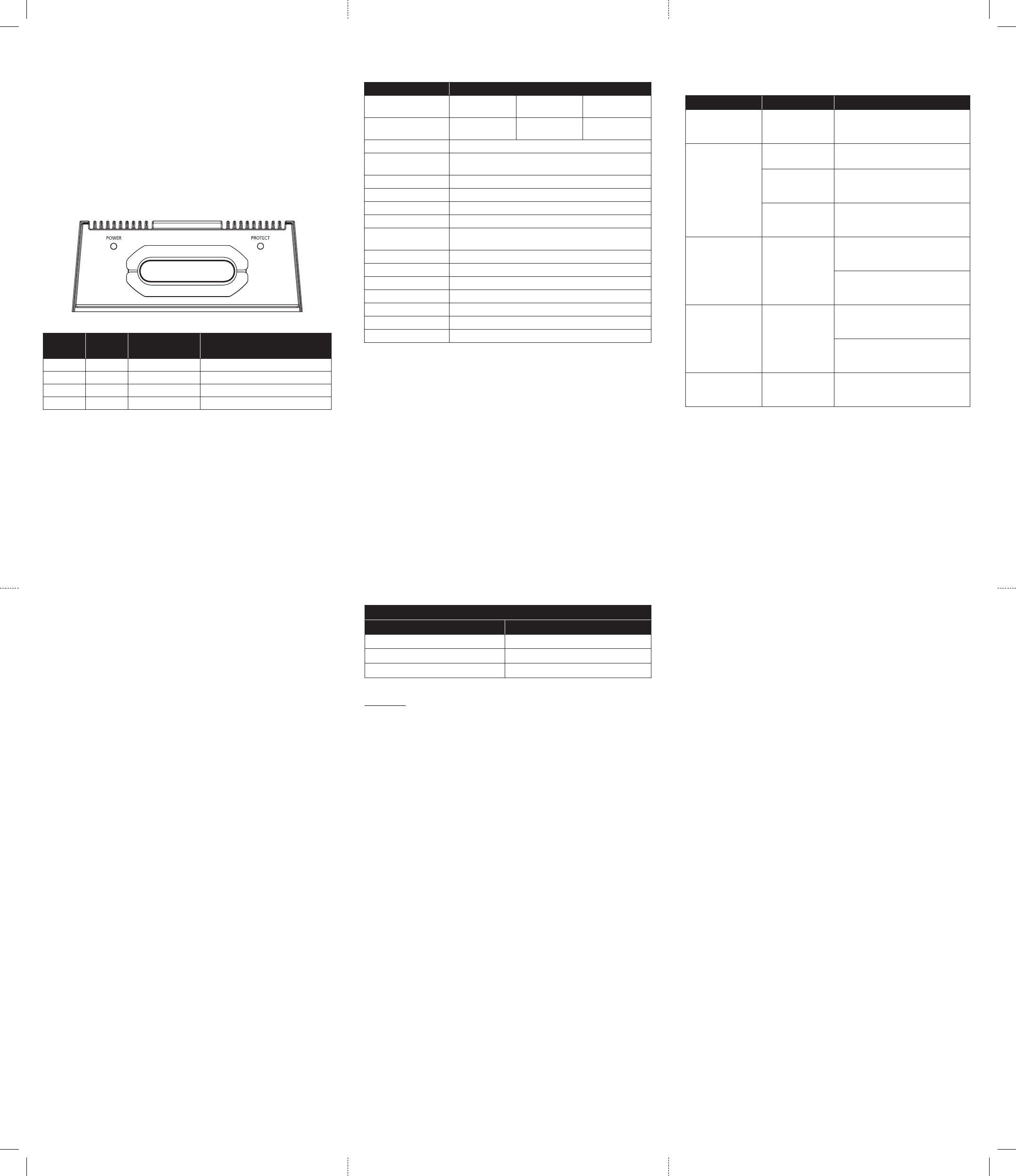
Status LED’s / Protection Circuitry
There are two status indicator lights on the wiring end panel of the amplifier.
1. POWER (Green): Lights to indicate that the amplifier is turned on and
operating normally.
2. PROTECT (Red): Lights to indicate the amplifier’s protection circuitry
has been activated to prevent product failure due to thermal overload,
over current or short-circuit to the amplifier’s outputs. When this pro-
tection mode is activated, the amplifier will shut down to protect its
circuitry. When the problem is corrected, the amplifier will return to
normal operation and the “Protect” LED will shut off. Connecting the
speaker outputs to impedances lower than 2 ohms will also cause this
protection mode to activate.
POWER
(Green LED)
PROTECT
(Red LED)
Status Note
ON OFF Normal Operation
OFF ON Thermal Protection Lasts until temp cools to normal
OFF/ON ON/OFF Over Current Green/Red LEDs alternate for 1 second
OFF ON Short Circuit Possible audible “popping” noise
2

Brauchen Sie Hilfe? Stellen Sie Ihre Frage.

Forenregeln

Missbrauch melden von Frage und/oder Antwort

Libble nimmt den Missbrauch seiner Dienste sehr ernst. Wir setzen uns dafür ein, derartige Missbrauchsfälle gemäß den Gesetzen Ihres Heimatlandes zu behandeln. Wenn Sie eine Meldung übermitteln, überprüfen wir Ihre Informationen und ergreifen entsprechende Maßnahmen. Wir melden uns nur dann wieder bei Ihnen, wenn wir weitere Einzelheiten wissen müssen oder weitere Informationen für Sie haben.

Art des Missbrauchs:

Zum Beispiel antisemitische Inhalte, rassistische Inhalte oder Material, das zu einer Gewalttat führen könnte.

Beispielsweise eine Kreditkartennummer, persönliche Identifikationsnummer oder unveröffentlichte Privatadresse. Beachten Sie, dass E-Mail-Adressen und der vollständige Name nicht als private Informationen angesehen werden.

Forenregeln

Um zu sinnvolle Fragen zu kommen halten Sie sich bitte an folgende Spielregeln:

Neu registrieren

Registrieren auf E - Mails für JL Audio MX500 wenn:


Sie erhalten eine E-Mail, um sich für eine oder beide Optionen anzumelden.


Andere Handbücher von JL Audio MX500

JL Audio MX500 Bedienungsanleitung - Englisch - 2 seiten


Das Handbuch wird per E-Mail gesendet. Überprüfen Sie ihre E-Mail.

Wenn Sie innerhalb von 15 Minuten keine E-Mail mit dem Handbuch erhalten haben, kann es sein, dass Sie eine falsche E-Mail-Adresse eingegeben haben oder dass Ihr ISP eine maximale Größe eingestellt hat, um E-Mails zu erhalten, die kleiner als die Größe des Handbuchs sind.

Ihre Frage wurde zu diesem Forum hinzugefügt

Möchten Sie eine E-Mail erhalten, wenn neue Antworten und Fragen veröffentlicht werden? Geben Sie bitte Ihre Email-Adresse ein.


Info