BUILT-IN TWEETER
PROTECTION CIRCUITRY:
The VR Crossover networks are equipped with
an advanced electronic tweeter protection circuit
designed to minimize the possibility of tweeter
failure. This electronic device monitors current
going to the tweeter and will disconnect the
tweeter from the signal when it senses overload.
Should this occur while listening to the audio
system, simply reduce the volume for a few
seconds and the protection circuit will reset
itself automatically.
ADJUSTABLE TWEETER LEVEL:
VR Crossover networks also provide two levels
of tweeter adjustability designed to compensate for
different mounting locations, vehicle interiors and
personal taste. The two levels are selectable via a
switch located on the top surface of each crossover
case. We recommend that you begin listening at
the “Reference” position. If the sound seems too
bright or aggressive, switch both crossover’s
switches to the “-3 dB” position. For quick A/B
comparison, it is safe to operate the switches while
the system is playing.
SPEAKER PLACEMENT
CONSIDERATIONS:
A component system gives you the ability to
place the woofer and tweeter separately in your
vehicle interior.This can be good or bad, depending
on how it’s done.
As a general rule, the tweeters should be placed
relatively close to the woofers for best tonal balance
and most coherent imaging (the closer, the better).
Any separation greater than 8 inches (20 cm) is
likely to result in degraded sound quality.
Avoid placing tweeters where they will be
blocked by objects in the interior of the car
(including seated occupants). When selecting a
mounting location, look at both sides of the car to
make sure that this location is clear on both sides.
You can always experiment with tweeter
placement before committing to a final mounting
location. Simply connect the rest of the system and
allow plenty of wire length for the tweeters. Using
velcro or similar material, attach the tweeters in
different locations until you find the one where they
perform best.
Woofers will usually be placed into factory
speaker locations. If you have some woofer
mounting flexibility, keep the followiing in mind:
Lower mounting locations, such as the lower front
corner of a door or a kick-panel provide the
greatest path length distances for the sound emitted
by the woofer. For this reason, they are generally
more desirable than higher mounting locations.
Higher mounting locations will usually result in
extreme near-side soundstage bias which
compromises the stereo listening experience.
JL AUDIO VR525-CSi 3
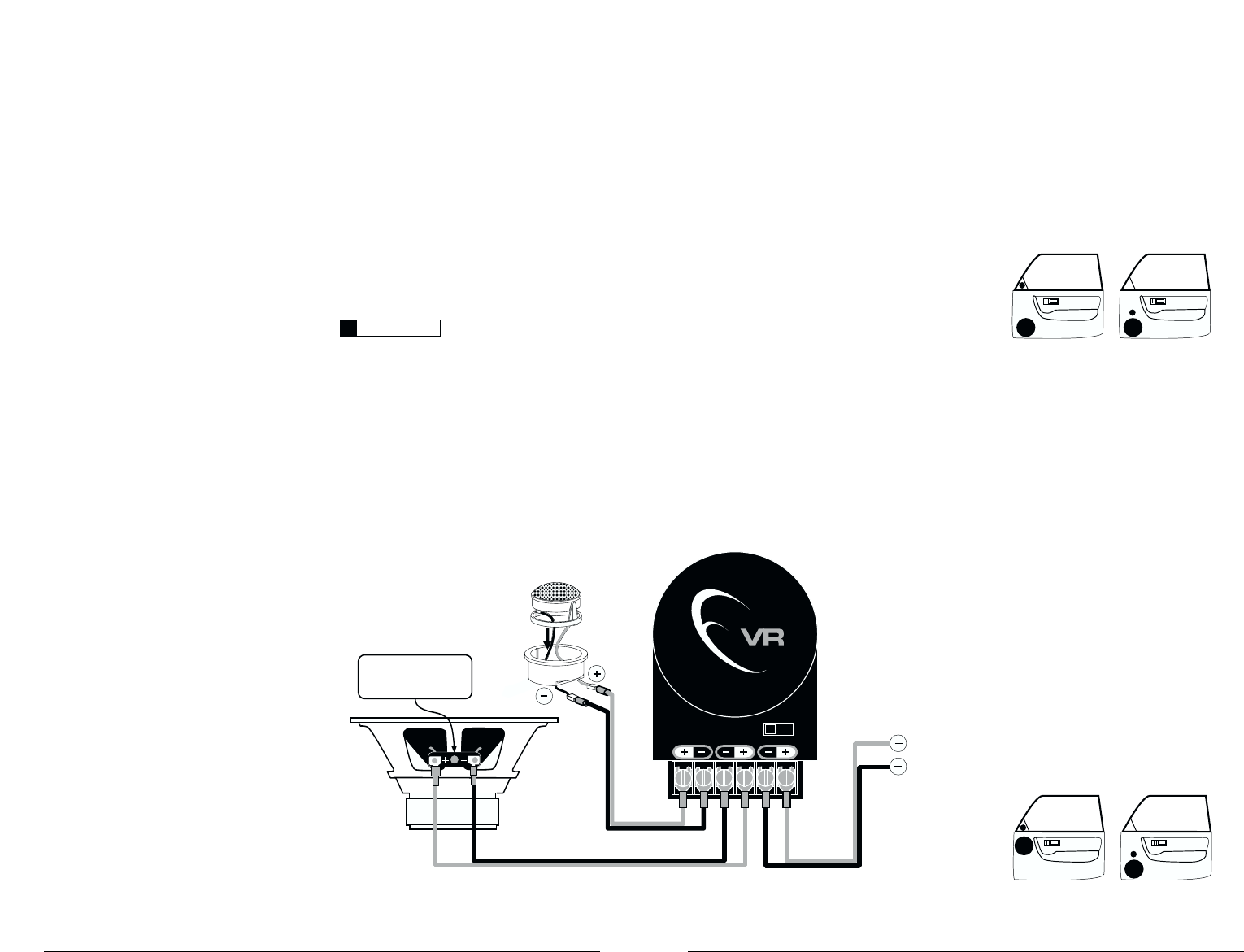
A) Wiring Diagram:
VR525-CSi SPECIFICATIONS:
Woofers: Injection-molded, mica-filled,
polypropylene cone body, 1-inch (25mm) voice
coil, flat-profile/symmetrical-roll spider, butyl
rubber surround.
Tweeters: 0.75-inch (19 mm) silk dome tweeter,
neodymium magnet, ferrofluid cooled and
damped.Variable mounting system with
swivel/rotation capability.
Crossover Networks: 2-way network with
natural low-pass roll-off and 4th order high-pass
circuit. Premium Mylar Capacitors and Air-Core
inductors. Adjustable tweeter output level.
Polyswitch tweeter protection.
Continuous Power Handling:
60 Watts (RMS Method)
Frequency Response: 63 Hz - 25 KHz (± 3 dB)
Efficiency @ 1W/1m: 87.5 dB
Nominal Impedance: 4 ohms
Included Components and Parts:
• Two VR525-CWi 5.25-inch (130 mm) woofers
• Two VR075-CT 0.75-inch (19 mm) tweeters
• Two VR525-CSxo 2-Way Crossover networks
• Two Flush-Mount tweeter fixtures with
metal spring clips.
• Two Surface-Mount tweeter fixtures.
• Two Metal Woofer Grilles and Grille Trays
• Butyl adhesive putty for woofer grilles
• Twelve #8 x 1 1/4-inch (30 mm)
sheet metal screws
• Four #6 x 5/8” (16 mm) sheet metal screws
• Two 1-inch (25 mm) machine screws
• Eight Mounting Clips
• Two 5.2 mm female crimpable connectors
• Two 2.8 mm female crimpable connectors
• Four 2.8 mm male crimpable connectors
• Four black nylon wire ties
GETTING STARTED:
• Turn off the audio system. It is also advisable to
disconnect the negative (-) terminal of your
vehicle’s battery whenever performing
installation work.
• Before cutting, drilling or inserting any screw,
check clearances on both sides of the planned
mounting surface. Also check for any potential
obstacles, such as window tracks and motors,
wiring harnesses, etc. Check both sides of the car,
many cars are not symmetrical!
• Always wear protective eyewear.
It is absolutely vital that your component
system is connected as shown in the diagram
below. Failure to connect the system as shown
will result in damage to your speakers which is
NOT covered under warranty. Do not substitute
different crossover networks into your VR525-CSi
System. Only use crossover networks clearly
marked “VR525-CSxo”.