5
1. PO WER SWITCH
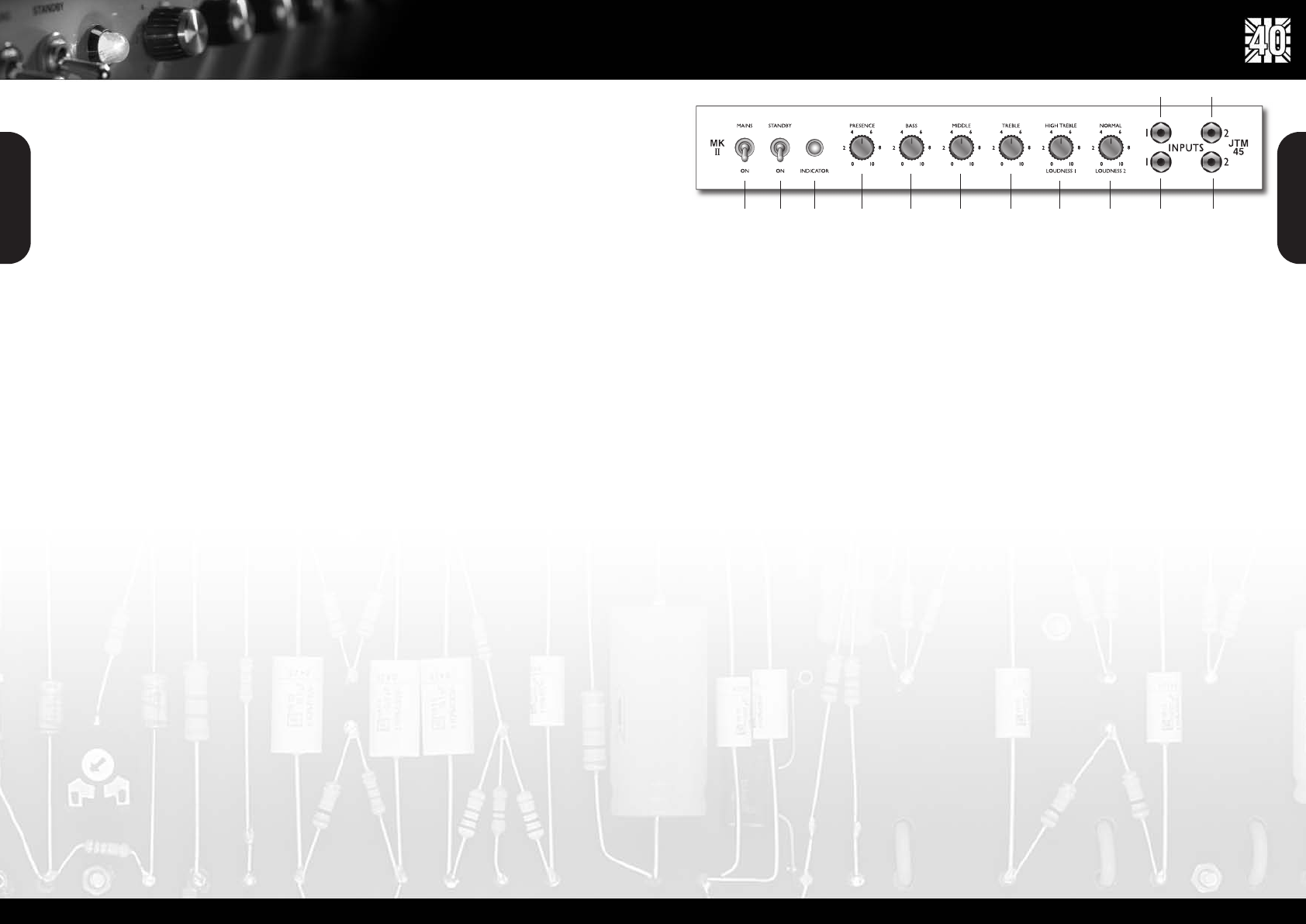
This is the On/Off switch for mains po wer to the
amplifier .
Note: Please ensure the amplifier is switched off and
unplugged from the mains electricity suppl y whenever it
is moved.
2. ST ANDBY SWITCH
The Standby Switch is used in conjunction with the
Po wer Switch (item 1) to 'warm up' the amplifier befor e
use and to prolong the lif e of the output valves.
When powering up the amplifier al wa ys engage the
P ower Switch first, lea ving the Standby s witch on
'Standby'. This allows the heater v oltage to bring the
valves to their corr ect operating temperature. After
appr oximately two min utes the valves will ha ve r eached
their correct operating temperatur e and the Standby
Switch can be engaged, enabling the HT without
'shocking' cold valves.
In order to pr olong valve life, the Standby Switch alone
should also be used to turn the amplifier on and off
during breaks in a perf ormance . Also , when switching
off, alwa ys disengage the Standby Switch prior to the
main Po wer Switch.
3. INDICA T OR
This 6.3 V olt incandescent filament indicator will light up
when your amplifier’ s heaters are energised at mains
power s witch on, (irrespectiv e of standby switch
position). It will not be lit when the amplifier is switched
off and/or is not receiving mains po wer .
4. PRESENCE CONTROL
This control operates in the JTM45/100's po w er section
and adds high fr equencies to your sound by altering the
pow er amplifier's negative f eedback. T urning this control
clockwise adds mor e 'sparkle' to your sound, making it
crisper and more cutting.
5. BASS CONTROL
This adjusts the bottom end, turning it clockwise
increases the amount of lo w frequencies in the sound.
6. MIDDLE CONTROL
This adjusts the lev el of those all-impor tant mid-range
frequencies. T urning it clockwise incr eases the mids and
fattens your sound, giving it mor e punch. T urning it
anticlockwise reduces the mids, pr oducing a more
'scooped' tone.
7.TREBLE CONTR OL
This adjusts the top-end. T urning it clockwise incr eases
the amount of high frequencies pr esent in the sound,
giving your guitar tone a brighter edge.
Note: The f ollowing four contr ols - PRESENCE (item
4), BASS (item 5), MIDDLE (item 6) & TREBLE (item 7)
- are all shar ed, meaning that they are common to both
Channel I and Channel II. They ar e highly interactive and
altering one control can change the wa y the others
beha ve. For this reason, experimentation is
r ecommended.
8. LOUDNESS 1
This controls the o verall output lev el of Channel I,
turning it clockwise increases the v olume. This channel
is voiced for a higher tr eble response than Channel II,
hence its 'High T reble' labelling.
9. LOUDNESS II
This controls the o v erall output level of Channel II,
turning it clockwise increases the v olume level.This
channel is voiced f or a 'normal', flatter response and is
labelled as the 'Normal' channel.
10. HIGH SENSITIVITY INPUT FOR
CHANNEL I
This is the 'high sensitivity' guitar input for Channel I, the
so called High T reble channel. It is the most commonl y
used input. Always use a high quality scr eened guitar
lead.
11. LO W SENSITIVITY INPUT FOR
CHANNEL I
This is the 'low sensitivity' guitar input for Channel I.
12. HIGH SENSITIVITY INPUT FOR
CHANNEL II
This is the 'high sensitivity' guitar input for Channel II,
the so called 'Normal' channel.
13. LO W SENSITIVITY INPUT FOR
CHANNEL II
This is the 'lo
w sensitivity' guitar input f
or Channel II.
Interesting aside: Back in the da y , a 'high sensitivity'
input jack was recommended f or use with a guitar
loaded with low-output pickups (e.g.: single coils) while
4
T one Circuit: In typical Marshall fashion, the JTM45/100’ s shar ed tone network is passiv e and interactive. By
interactive w e simply mean that the settings of the Bass and T reble contr ols affect the amount of mid-dip (cut)
a vailable via the Middle control.
T ag Boar ds: The tag boar ds used in your hand wired r e-issue are exactly the same as those in the original in terms
of thickness and matrix pitch. The material we'r e using is made exclusively f or us and is ‘UL r ecognised Micom type
Marshall EM42’. The reason w e didn’ t use a board with the exact same chemical composition as in the original units is
because that material doesn't pass curr ent safety requir ements regarding flammability .
T ransformers: The mains (po wer) and output transformers ar e vital to the performance, sound and feel of an all-
valve amplifier . Because of this we spent a gr eat deal of time studying and analysing the constructional methods and
materials used in the original transformers so w e could match everything as closely as possible. W e also w ent to great
lengths to ensure that the all-important electrical characteristics and performance of the originals w ere duplicated
exactly . In or der to achiev e these vitally important goals we w orked extr emely closely with our associates in the R&D
department of Drake – the compan y which supplied us with the output transformers used in the original JTM45/100.
Mains (P o wer) T ransformer : In the original JTM45/100 the mains transformer was an “off-the-shelf ” device
purchased fr om a highly r egarded general electronic components supplier . Referr ed to as the “RS De Lux e ”this
transformer is no longer a vailable, but with the help of Drake’ s expertise w e were able to r eplicate the performance
of the original “De Luxe” of which we ha v e several genuine examples.W e paid particular attention to an important
electrical effect called ‘regulation’ which is the variation in beha viour of the HT voltage and curr ent from the
transformer and is dependant on load demand (i.e. how loud you’ re pla ying!). This behaviour aff ects how the amplifier
compresses and r eacts to saturation when pla yed at high volumes – hence its importance.
Output T ransformers: As already mentioned, the pair of output transf ormers used in the original JTM45/100s wer e
supplied by Drak e, as are those in your r eissue . F or tunatel y Drake still had their original documentation intact after all
of these years, a factor which obviousl y helped ensure that the reissues ar e 100% accurate.
P o wer Suppl y: This cir cuit has the same exact filtering on the H.T . (high voltage DC, a.k.a. the B+ voltage) line as the
original versions, a factor that contributes to the JTM45/100 ha ving a unique, dynamic characteristic all of its own.
Chassis: W e are using a box-section chassis made fr om 16-gauge mild steel with butt-welded corner joints.The steel
is also passivated giving lifelong r esistance to corr osion.
Fr ont Panel: Extra thick, gold colour ed Plexiglas (actually P erspex, causing some people to refer to it as ‘Perplexi’!),
exactly as the original. Specific details pertaining to the front panel featur es can be found on page 5 of this manual.
Rear Panel: Made fr om cream styr ene with gold print, just lik e the original refer ences.
Head Cabinet Construction: High-grade, flawless (knot-fr ee) Baltic birch-ply with finger lock ed joints for maximum
strength. The main cabinet frame (sides, top and bottom) ar e 15mm ply , the fr ont baffle is constructed fr om 12mm ply
while the back of the cabinet is 9mm ply . All edges hav e a 15mm radius.
Head Cabinet Cosmetics: The Marshall Block log o , black Levant cov ering, original venting, beading and piping
duplicate the look and style of the originals.
ENGLISH
ENGLISH
Fr ont panel featur es
1 2 3 4 5 6 7 8 9 11 13
12 10