Fi
ho
wa
mo
pl
wi
to a
(D
ot
1. D
si
by m
2. Dφ 65
3. D
ho
4. Alw
me
1. F
r
em
2. F
p
ip
3. B
d
ra
s
ho
Be
of t
bo
an
1. R
D
o no
i
n Fi
2
. Wh
i
ns
d
ra
t
he d
Co
ou
Do n
ba
Be c
He
Be s
th
th
ov
Ne
wi
Ru
dr
1. P
2
. Ho
o
f in
t
he u
t
he h
p
la
3
. Pi
u
ni
i
nd
p
ip
4
. Pr
a
ga
e
ng
INST
AIR CONDITIONER
(Split W
D
F
2
C
3
C
D
C
I
1
"
I
N
D
O
O
R
U
N
I
T
C
o
1
2
3
4
5
7
8
9
6
In
Cl
Se
Se
Dr)
C
p
A
L
G
Re
Se
Φ6
Φ9
Φ9
Φ1
Φ
Pa
si
Co
si
1
5
5
1
1
1
2
1
Ex
pu
Re
A
N
N
Q
N:
o
p
O d
m x
A m
4
B m
2
5
6
2
3
5
5
4
4
3
2
2
2
M n i e
7 x
7 x
7 x
8 x
7 x
6 x
6 x
S
Th
Th
1) This equipmen
elec shoc if g is not perfe
2) Do not
accu
3) Ca
may
1) In
leak e sho fir
2)
t
to f w le elec shoc fire
3
) Ins
enou or insta is n pro done, the set will dr and cause i
4
) For electric
An i c and singl outl mus be used. If elec capac is not eno or
defe foun in elect work, it will cause e sh fi
5
) Use the
on t ter conne or f is n per it wi cau hea o fire at the connecti
6
) Wir
cove is n fix per it will cau hea a conn o term fire or e sho
7
) Whe
refri into refriger cycle Othe will cause l c ab pre
in t ref c explo a inj
8
) Do
sing out wi oth ele Ot it will cause fi or electric sho
S
C
W
C
W
Please read this installation manual completely before installing the product.
If the power cord is damaged, replacement work shall be performed by authorised personnel only
Installation work must be performed in accordance with the national wiring Standards by authorised
personnel only
Contact an authorised service technician for repair
This appliance is not intended for use by persons(including children) with reduced physical, sensory
or mental capabilities, or lack of experience and knowledge, unless they have been given supervision
or instruction concerning use of the appliance by a person responsible for their safety
Children should be supervised to ensure that they do not play with the appliance.
The design and specifications are subject to change without prior notice for product improvement.
Consult with the sales agency or manufacturer for details.
All the pictures in the instructions are for explanation purposes only
Th
ne
Th
ai
A
A
A
co
Do n
En
wa
Th
su
I
O
If a
di
ra
Th
co
Ke
ce
Do n
a sh
Anφ 10 o
φ8 ti
S
NO Th
of t
di
B
D
A
A
A
W
A
1. F
on s
sp
2. I
or t
ho
ap
3. F
wi
N
N
F
Th
en
"
"
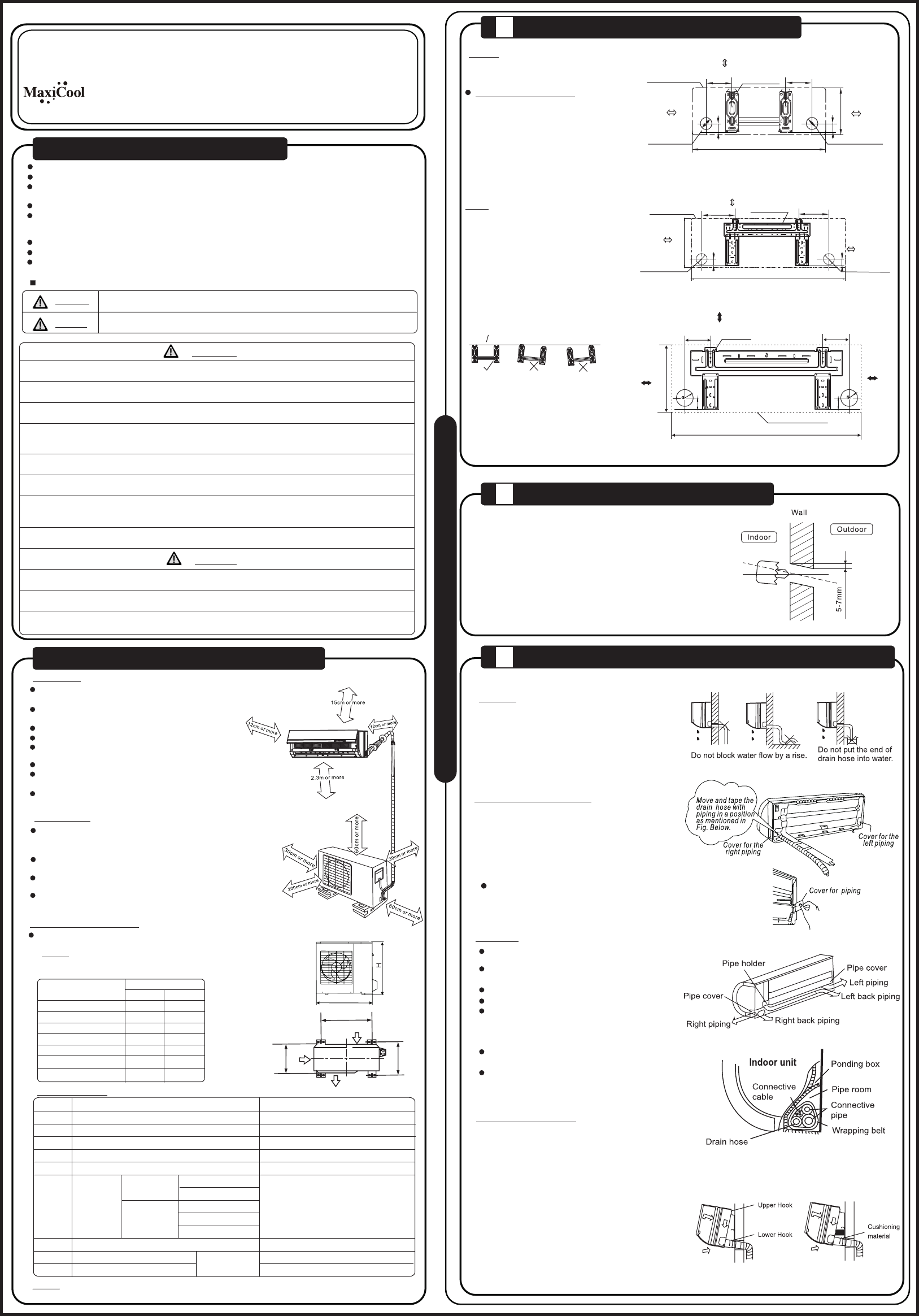
150 or more to ceiling
Indoor unit outline
Installation plate
292
Right rear side
refrigerant
pipe hole φ 65
Left rear side
refrigerant
pipe hole φ 65
120 or more
to wall
120 or more
to wall
920
45
1
1
45
A
45
B
Right rear side
refrigerant
pipe hole φ 65
Installation plate
Indoor unit outline
Left rear side
refrigerant
pipe hole φ 65
150 or more to ceiling
120 or more
to wall
120 or more
to wall
M
M )
M
M
45
C
D
120mm or more
from the wall
120mm or more
from the wall
4
150mm or more from the ceiling
Indoor Unit Outline
Hooked Part
65
65
4
9
1
1
3
2