A
4
5
Liquid side:φ 6.35mm
R22: (Pipe length-5)x30g/m
R410A: (Pipe length-5)x20g/m
Liquid side:φ 9.52mm:
R22: (Pipe length-5)x60g/m
R410A: (Pipe length-5)x40g/m
Connective pipe length
Less than 5m
More than 5m
Air purging method
Use vacuum pump
Additional amount of refrigerant to be charged
Op
th
Se
a sp
V
Tig
.
.
.
.
Flare nut
Stopper
Cap
V
V
Use vacuum pump
Fo
fo
Wh
.
.
.
.
Ai
an
an
Ch
be
Pi
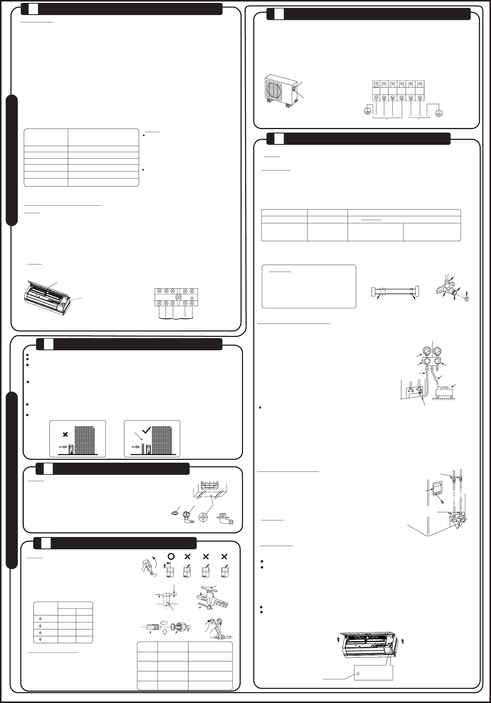
Outdoor
unit
Indoor
unit
Refrigerant
Packed valve
Half union
Gas side
Liquid side
A
C
D
B
1. C
t
he m
p
ac
2
. Co
p
um
3
. Fu
4
. Op
e
va
v
al
e
nt
a
nd a c
5. Aft
e
L
o of t
v
ac
Ma
5
th Pa
O
6
. Turn t co
cl
ti
in t
pr
7
. Re
8
. Fu
9
. Se
Manifold valve
Compound meter
-76cmHg
Handle Lo
Handle Hi
Charge hose
Charge hose
V
Pressure gauge
Packed valve
Pe
sa
Ch
Ch
1. C
2. U
we
O
3. Wh C)
re
us
Ho
Pr
AU
4. Th
1
2
4
3
A: L
C an
CA
1. S
Ap
un
to c
bu
2. Le
Us
C
CAUTION
Indoor unit
check point
D
B
C
A
Outdoor unit
check point
Cover
Electrical box
cover
Front Panel
Ma
bu
AUTO/COOL
,
C
Be
1. T
2. T
in
3. L
4. E
re
5. W
an
N
NOTE: If used as MONO unit, for the standby control needs, the cross section area of cable connected
to L(1), 1, 2(N) must be sufficient for the maximum system current.
equal to the sum of indoor unit and outdoor unit rated current.
T
T
L(1)
2(N)
S
1
1. Rem
2. Con
s
on the ter
3. Sec
4.
di
5. Ins
l
or met
Cover
Screw
T
T
Power supply
1
2(N)
S
L N
L(1)
I
N
D
O
O
R
U
N
I
T
C
4
In
De
In t
su
or s
Sp
in
in
in
Th
st
Be s
S
w
S
w
B
I
C
Se
Dr
Ba
of o
(
(
Th
di
Fo
th
。
ho to s
T
jo
fi
an e
wa
2
D
O
3
Oblique
O
90
Roughness
Burr
R
1. C
2
. Re
o
ut
h
av
t
he p
3
. Fi
d
im
.
.
Al
Su
an
wr
Ex
on i
Outer diam.
(mm)
A(mm)
Max.
Min.
6.35 1.3
0.7
9.52
1.6 1.0
12.7
1.8 1.0
12.7
16
1.8
2.2
1.0
2.0
Bar
Copper pipe
Clamp handle
Handle
Bar
"A"
Indoor unit tubing Flare nut Pipings
.
Outer
diam.
T
torque(N.cm)
Additional tightening
torque(N.cm)
φ6.35mm
φ12.7mm
φ16mm
φ9.52mm
1500
(153kgf.cm)
1600
(163kgf.cm)
3500
(357kgf.cm)
4500
(459kgf.cm)
3600
(367kgf.cm)
4700
(479kgf.cm)
2500
(255kgf.cm)
2600
(265kgf.cm)
F
T
O
U
T
D
O
O
R
U
N
I
T
1
NO
El
1. If
th
2. Pow
3.
be ins
4. D
co
5.
cu
cu
wi
6. For the uni
ma
7.
un
by qua
8.
Se
M
R
o
(
>3 ≤6
>6 ≤10
>10 ≤16
>16 ≤25
>25 ≤32
>32 ≤40
N
a
(
0.75
1
1.5
2.5
4
6
E
Th
in
th
ma
na
of the uni
be
Th
wi
ab
th
su
N
N
C
n