Install the outdoo
Determine the air o
In the cas
sure the f
or shield p
Specially in wind
installation, the in
installation bracket diag
intensity construction, o
The connection
stable and reliab
Be sure th
Strong
wind
Strong
wind
Barrier
Incorrect
Correct
Seal
Drain joint
Base pan
of outdoor
(A)
(B)
The drain joint is slightly
different outdoor unit.
For the drain joint with
the drain joint, then insert
hole of outdoor unit, rotate to securely assemble them.
To
joint into the base pan
fixed with a clicking sound.
an extension drain hose (Locally
water draining off the outdoor
2
DRAIN JOINT INST
OUTDOOR IN
3
REFRIGERANT
1. Cut a pip
2. Put flar
completed burr remov
3. Firmly
dimension shown in th
Align pipes to be co
Sufficiently tigh
and then
wrench as show
Excessive torque can bre
on installation c
Outer diam.
(mm)
A(mm)
Max.
Min.
6.35 1.3
0.7
9.52
1.6 1.0
12.7
1.8 1.0
12.7
16
1.8
2.2
1.0
2.0
Bar
Copper pipe
Clamp handle
Handle
Bar
"A"
Indoor unit tubing Flare nut Pipings
Outer
diam.
Tightening
torque(N.cm)
Additional tightening
torque(N.cm)
6.35mm
12.7mm
16mm
9.52mm
1500
(153kgf.cm)
1600
(163kgf.cm)
3500
(357kgf.cm)
4500
(459kgf.cm)
3600
(367kgf.cm)
4700
(479kgf.cm)
2500
(255kgf.cm)
2600
(265kgf.cm)
AIR PURGING AND
4
5
1. Remove the ele
2. Connect the con
3. Secure the cabl
4. To prevent the in
5. Insulate unuse
or metal parts.
Cover
Screw
Ter
Liquid side: 6.35mm
R22: (Pipe length-5)x30g/m
R410A: (Pipe length-5)x15g/m
Liquid side: 9.52mm:
R22: (Pipe length-5)x60g/m
R410A: (Pipe length-5)x30g/m
Connective pipe length
Less than 5m
More than 5m
Air purging method
Use vacuum pump
Additional amount of refrigerant to be charged
Open the valve ste
the stopper. Do not try to open it furt
Securely tighten the valve stem ca
a spanner or the like.
Valve stem cap tightening to
Tightening torque ta
Flare nut
Stopper
Cap
Valve body
Valve stem
Use vacuum pump
For the R
form in an
When relocating the unit to
The indoor unit and tubing
to remove any noncondensables and
Check that each tube(both liquid
been properly connected and all
Pipe length and refrigerant amount:
Outdoor
unit
Indoor
unit
Refrigerant
Packed valve
Flare nut
Gas side
Liquid side
A
C
D
B
1. Completely tig
the manifold v
packed valve o
2. Connect the ch
pump.
3. Fully op
4. Operate the vac
evacuation, slightly lo
valve on the ga
entering. (Operation n
and a c
5. After the ev
Lo of th
vacuum pump.
Make evacuation for 1
5
that the compo
O
6. Turn the ste counter-
clockwise for 6
tighten the fla
in the p
pressure.
7. Remove the cha
8. Fully op
9. Securely tight
Manifold valve
Compound meter
-76cmHg
Handle Lo
Handle Hi
Charge hose
Charge hose
Vacuum pump
Pressure gauge
Packed valve
Perform test operation after completing
safety check.
Check that all tubing and
Check that the gas and
1. Connect the power
2. Use the MODE button
well.
O
3. When the ambient temperature
remote controller to run at
used only when the remote
Hold the panel sides and
Press the Manual control button
AUTO or COOL
4. The test operation should
Flaring
Tightening
1. Air
2. When
4. T
3. Safety
A: Lo pac
C and D ar
CAUTION
1. Soap water method:
Apply a soap
unit connections and outdoor unit
to check for leakage of
bubbles come out, it indicates
2. Leak detector
Use the leak detector to
O
U
T
D
O
O
R
U
N
I
T
CONNECT THE CABLE
CAUTION
1
Indoor unit
check point
D
B
C
A
Outdoor unit
check point
Cover
NOTE:
To indoo
To indoo
Power supply
Model A
Model B
Power supply
Oblique
Roughness
Burr
O
90
AUTO/COOLAUTO/COOL
Manual control button
Connect the i
outdoor unit.
Do not allow the p
back of the ind
Be careful no
Heat insulation should be d
extension drain hose of ind
Be sure that the d
the lowest sid
the upper sid
overflow inside the unit.
Never intercross nor inte
wire with any ot
1. Pass the
2. Hook the
of installation pla
the upper edge of th
the hooks are prop
plate by moving i
3. Piping c
unit with a cushio
indoor unit and th
piping.
4. Press th
against the insta
engages with th
CAUTION
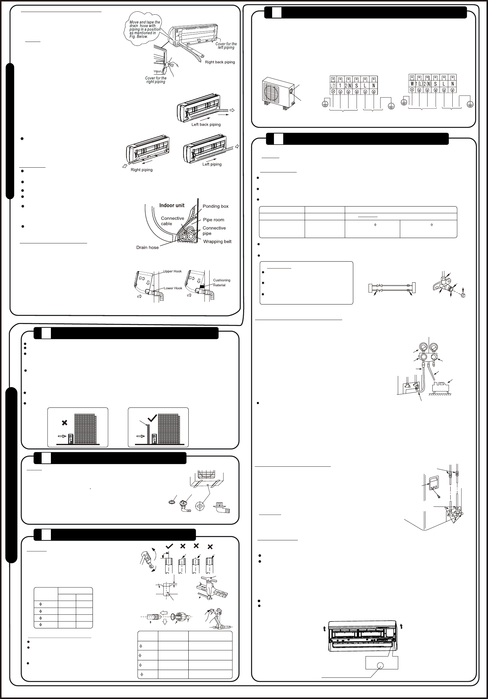
Indoor unit in
1. For the le
remove the pip
2. For the ri
install the pipin
NOTE:
3. Bundle the tubin
drain hose with ta
shown in Figure
For 9K/12K mode
side drainage s
model, one side d
Both sides drai
and can only be cu
For both sides dr
choosen for righ
connection. If ch
connection, another pro
needed as ther
by factory. If choosin
connection, make sure th
other side is well p
the drain hose is s
qualified installer in case
Connective
Because the condensed water from
of the indoor unit is
box and is piped out
anything else in the box.
I
N
D
O
O
R
U
N
I
T
NOTE:
Connective pipe length
nominal efficiency is