Detach the Front Panel
Press button in the upper left corner, and then the front panel will be folded down.
When the front panel was turned down to the angle of 45°, hold and push the front
panel to left, and then pull it out.
POWER button
(release button)
SEL/VOL knob (Audio/ volume)
SD/SDHC/MMC card slot
LCD display
TA button (Trafc Announcement)
AF button (Alternative Frequency)
Reset button
USB port with lid
AUX in jack
0/DSP button (Display time)
PTY button (Program type selection)
6/DIR+ button (Directory up)
Do not attempt to modify the unit, modifying the unit may cause an accident.
Installation or servicing of the unit by persons without training and experience in
electronic equipment and automotive accessories may be dangerous and could
expose you to the risk of electric shock or other hazards.
Stop the vehicle before carrying out any operation that could interfere with your
driving.
Keep the volume at a level which you could hear sounds from outside the vehicle.
Do not work in extremely high or low temperature. Be sure the temperature inside
the vehicle is between +60°C and -10°C before turning on your unit.
When replacing the fuse(s), the replacement must be of the same amperage as
shown on the fuse holder.
Do not block vents or radiator panels. Blocking them will cause heat to build up
inside and may result in re.
Using this unit without running the engine can result in battery drainage
Use only in cars with a 12 volt negative ground.
After completing the installation or replacing the car battery you need to RESET the
unit before using it. Remove the front panel and press RESET button on the base
with pointed object (such as ball-point pen) to reset the unit to its initial settings.
1.
2.
3.
4.
5.
6.
7.
8.
9.
10.
GB - 1
M-092 MR
User Manual
CAR RADIO WITH USB & SD
Please read the instructions carefully before
operating the unit.
PRECAUTIONS
English
GB - 2
GB - 3
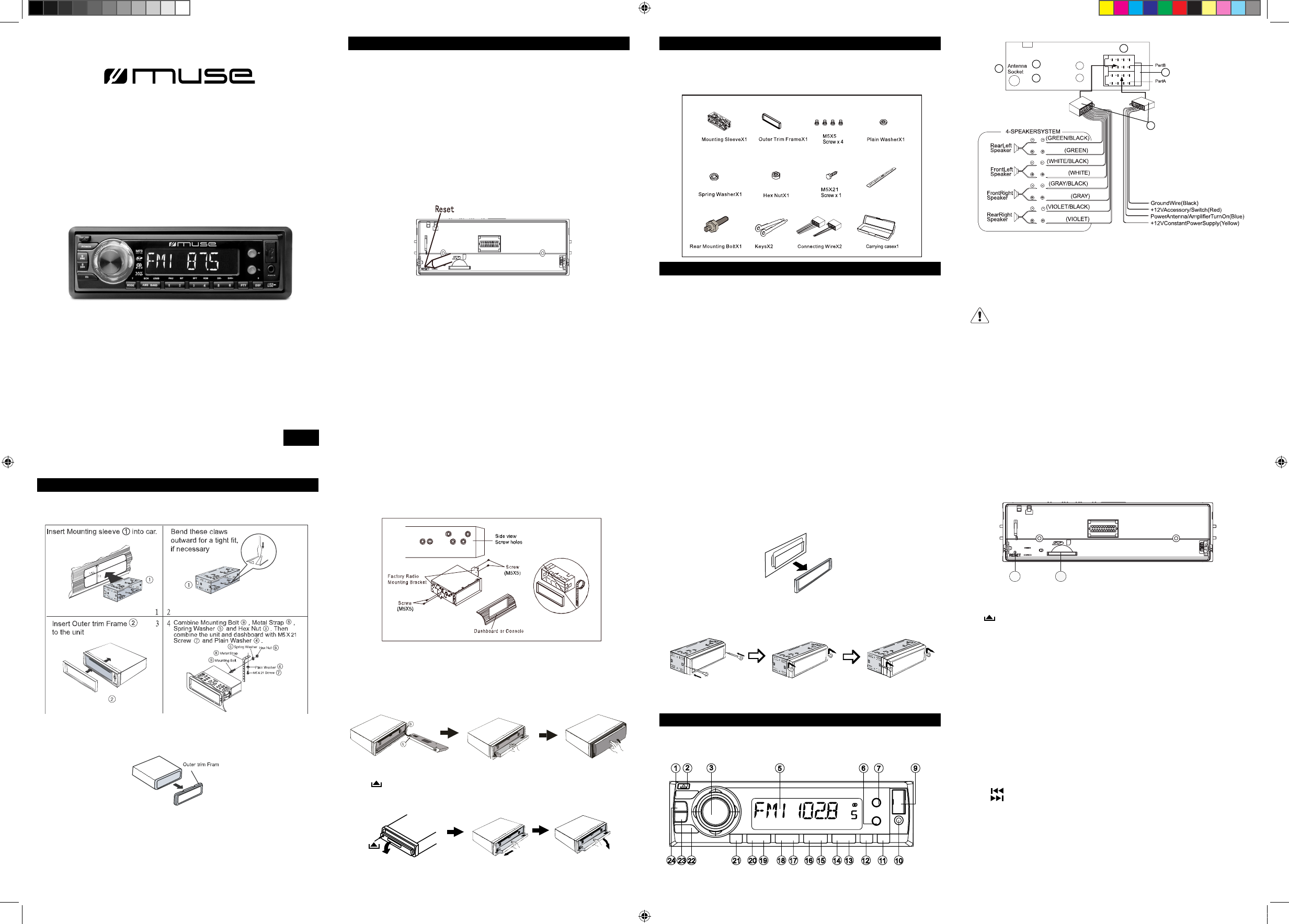
CONNECTION
1. Antenna socket
2. Line out (Right-Red)
3. Line out (Left -White)
4. Output plug (male)
5. Output plug (female)
6. Fuse holder (5A)
Caution!
- Make sure to connect the colour coded leads according to the diagram. Incorrect
connections may cause the unit to malfunction or damage the vehicle’s electrical sys-
tem.
- Make sure to connect the speaker (-) leads to the speaker (-) terminal. Never con-
nect the left and right channel speaker cables each other or to the vehicle body.
- Make sure all the connections are completely correct before turning on your unit.
GB - 5
Install the front panel
Put notch A (Shown as picture) onto shaft B. And then slightly press into the right side.
Note: Never put any objects into the front panel.
Detach the Unit
1. Detach the front panel. (Please refer to upper part)
2. Take out the outer trim frame.
LOCATION OF CONTROLS
Front panel
GB - 7
- Method 2 DIN Rear-mount (For Japanese car)
1. Remove the outer trim frame
UNPACK YOUR UNIT
When you unpack your new car radio, make sure that you have removed all the acces-
sories and information papers:
Main unit with connector
User manual
Accessories:
Install the unit
- Method 1: DIN Front-Mount
INSTALL AND REMOVE THE UNIT
2. Select a position where the screw holes of the mounting bracket supplied with the
car and the screw holes of the main unit become aligned (are tted).
Base
5/DIR- button (Directory down)
4/RDM button (Random)
3/RPT button (Repeat)
2/INT button (Intro)
1/PAU button (Pause)
BAND/LOUD button
AMS/SCH button (Automatic scan and
memorising)
7/MODE button
EQ button (equalizer)
8/ button (skip backward)
9/ button (Skip forward)
3. Tighten the screws. And then fasten them to the car.
3. Insert the keys supplied on the both sides of the unit (shown as illustrated) until
they click. Pulling the keys and makes them to remove the unit from the dashboard.
1.
2.
3.
4.
5.
6.
7.
8.
9.
10.
11.
12.
13.
GB - 4
14.
15.
16.
17.
18.
19.
20.
21.
22.
23.
24.
23 24
8
4
1
2
3
4
5
6