ES ES
ES ES
IT/MT
5.
1
al c
Fare attenzione a che tra la porta anti insetti e il bordo superiore dell’intr
so deve esser
posizionamento e una chiusura della porta anti insetti senza problemi.
6.
1
al
1
.
7.
1
per mezzo delle viti a testa svasata B
1
al telaio
all’altezza dei magneti
1
(vedi fig. J).
Inserire anche la terza molla
1
qualora si desiderasse av
di chiusura più forte.
Q
Montaggio del t
di autochiusur
j
meccanismo di autochiusura”.
j
1
fino all’estremità della dentellatura
(vedi fig. H).
In nessun caso tagliare il traversino completo. In caso contrario la cerniera
diventerebbe inservibile.
j
1
nelle cernere superiori
9
(vedi fig. I).
j
con meccanismo di autochiusura”.
Q
Pulizia e manutenzione
j
1
e il telaio con un panno privo di peli e leggermente
umettato.
j
j
j
Q
Smaltimento
questi rifiuti nei contenitori locali di riciclaggio.
Informazioni sulle possibilità di smaltimento del prodotto consumato sono disponibili presso
la sede dell’amministrazione comunale e cittadina.
Q
Produttore
FeinHeim GmbH
Bischof-Otto-Str. 60
D-94486 Osterhofen
Servizio Clienti +49-9932-40 25 897
Email: info@feinheim.de
V
Q
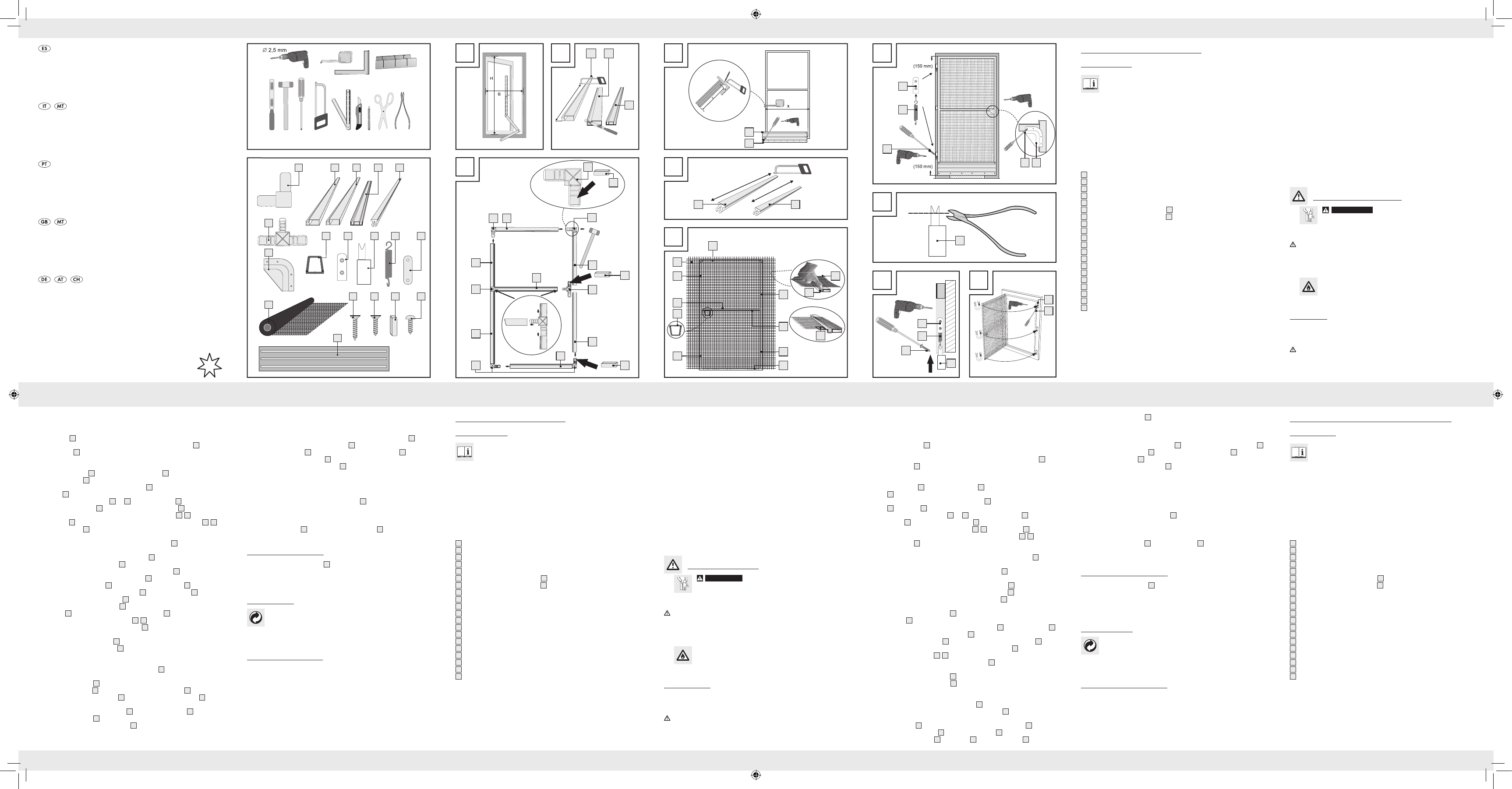
Montaggio del telaio
1.
(vedi fig. A).
2.
profili di alluminio A
2
con una sega e una cassetta di taglio fino a far loro raggiun-
gere la misura v
3.
3
e la
sbarra centrale
4
con una sega e una cassetta di taglio fino a far loro raggiunger
misura verificata (vedi fig. B).
4.
5.
1
in due connettori angolari
1
e in un connettore di sbarra centra-
le
6
(vedi fig. C).
Fare attenzione a che i connettori angolari
1
e il connettore di sbarra centra-
le
6
con magneti
1
si trovino sul lato che in seguito si tr
6.
2
e B
3
nonché la sbarra centrale
4
con connetto-
ri angolari
1
e connettori di sbarra centrale
6
secondo quanto mostrato nella figura
C. Fare attenzione a che i profili di alluminio
2
,
3
e sbarra centrale
4
siano posti
correttamente. Fare attenzione a che le cavità dei pr
2
,
3
e della
sbarra centrale
4
siano tutte rivolte verso un solo lato. Se necessario utilizzar
martello di gomma.
7.
1
con una
sega e una cassetta di taglio fino a far loro raggiunger
Fare attenzione a che il listello paraurti di alluminio
1
sia montato sul lato
senza cavità.
8.
1
al telaio (vedi fig.
D). Fare attenzione a che le posizioni delle viti a testa r
1
corrispondano con
quelle mostrate nella figura D. In caso contr
1
può impedire un fissag-
gio corretto.
9.
5
fino a farli diventare della misura dei pr
alluminio A
2
(vedi fig. E).
3
e
4
e accorciare gli altri quattr
5
alla misura corrispondente (vedi fig. E).
1
sopra il telaio. Inserire il passante di presa
8
secon-
do quanto mostrato dalla figura F
1
ai lati opposti per
mezzo dei listelli a scatto
5
,
5
.
Fare attenzione a che la rete di fibr
1
sia sufficientemente tesa. Se
necessario ripetere il passo 11.
1
in eccesso con la taglierina (vedi fig.).
7
secondo quanto mostrato dalla figura G
Q
Montare il telaio con meccanismo di aut
1.
9
. Fare attenzione a che la distanza
tra bordo superiore e inferior
9
è di almeno 15 cm.
Eseguire i fori (vedi fig. G).
2.
1
n
9
(v
3.
9
con viti a testa svasata A
1
al telaio (vedi fig. G).
4.
1
sopr
1
nell
9
(v
4 x Connettore angolar
4 x Profilo di alluminio A
2 x Profilo di alluminio B
1 x Sbarra centrale
8 x Listello a scatto
2 x Connettore di sbarra centr
1 x Maniglia a conchiglia
1 x Passante di pr
3 x Cerniera superiore
3 x Cerniera inferiore
3 x Molla
3 x Piastra di chiusura
1 x Rete di fibr
6 x Vite a testa svasata B
3 x Magnete
1 x Listello paraurti in alluminio
1 x Istruzioni di montaggio
Istruzioni di sicurezza
J
AT
PERICOLO DI VIT
BAMBNon l
imballaggio od il prodotto stesso. C’è pericolo di soffocamento con i mate-
pericoli. Tener
ATT As
senza danni e secondo le istruzioni. Se montati in modo inappropriato costituiscono
pericolo di ferite. Componenti danneggiati possono compromettere la sicurezza e la
funzionalità.
J
J
ATTENZIONE! PERICOL Non accendere fuoco nelle
immediate vicinanze del prodotto.
J
Q
Montaggio
Prima di eseguire il montaggio assicurarsi che la porta dell‘utilizzatore sia adatta a questo
prodotto e che non vengano super
AT Per eseguire il montaggio è necessaria
una sega, una taglierina e un trapano a batteria. E‘ assolutamente necessario tenere conto
delle istruzioni d‘uso degli utensili da utilizzare. Indossare guanti di pro
Zanzariera in alluminio per port
Q
la prima volta. Leggete le seguenti istruzioni di montaggio e le avvertenze di
sicurezza. Utilizzate questo prodott
indicati. Conservate bene queste istruzioni. Consegnate altrettanto tutte le documentazioni
su questo prodotto quando lo date a terzi.
Q
Utilizzo determinato
Questo prodotto è concepito per pr
stico. Un altro impiego rispetto a quello sopra descritto o la modificazione del pr
sono ammessi e possono causare ferite e
si assume alcuna responsabilità per danni causati da un utilizzo non conforme al pr
prodotto non è concepito per l‘impiego in settori commer
Q
Descrizione dei componenti
1
Connettore angolare
2
Profilo di alluminio A
3
Profilo di alluminio B
4
Sbarra centrale
5
Listello a scatto
5
Listello a scatto (Profilo di alluminio A
2
)
5
Listello a scatto (Profilo di alluminio B
3
)
6
Connettore di sbarra centrale
7
Maniglia a conchiglia
8
Passante di presa
9
Cerniera superiore
1
Cerniera inferiore
1
Molla
1
Piastra di chiusura
1
Rete di fibra di v
1
Vite a testa svasata A
1
Vite a testa svasata B
1
Magnete
1
Vite a testa rotonda
1
Listello paraurti in alluminio
Q
Dati tecnici
Max. dimensioni della porta: 100 x 210 cm
Q
Contenuto della confezione
Nota: Fare attenzione durante il disimballaggio a non gettare err
destinato al montaggio. V
nuto della confezione nonché le condizioni del prodotto e di tutti i suoi componenti. Non
montare assolutamente il prodotto se il contenuto della confezione non è com
PT
Procure que entre la mosq
nos 1 cm de separación. De otro modo no se gar
la mosquitera.
6.
1
mediante un tornillo de cabeza avellanada A
1
en el marco de la puerta.
7.
1
mediante tornillos de cabeza avellanada B
1
en los
marcos en la altura de los imanes
1
(véase fig. J).
Coloque también el tercer muelle
1
, si desea un mecanismo de autocierre
más fuerte.
Q
Montar los marcos sin mecanismo de autocierr
j
j
1
hasta el final de la muesca
(véase fig. H).
En ningún caso per
más la bisagra.
j
1
en la parte superior de la bisagra
9
(véase fig. I).
j
Q
Limpieza y cuidados
j
1
y el marco con un paño húmedo sin pelusas.
j
j
j
Q
Eliminación
Deséchelos en los contenedores de reciclaje locales.
Pue
de su comunidad o ciudad.
Q
Fabricante
FeinHeim GmbH
Bischof-Otto-Str. 60
D-94486 Osterhofen
Atención al cliente +49-9932-40 25 897
Correo electrónico: info@feinheim.de
Fecha de la información: 01
Q
Montar marcos
1. Mida primero el mar
2.
alu
2
me
3.
3
y el trave-
saño central
4
mediante la sierra y la caja de ingletes a la medida facilitada
(véase fig. B).
4.
5.
1
en dos empalmadores angulares
1
y un empalmador de
travesaño centr
6
(véase fig. C).
Compruebe que el empalmador angular
1
y el empalmador de travesaño
central
6
se encuentran en el lado contrario al que luego se colocarán las bisagr
6.
2
y B
3
y el travesaño centr
4
por medio de las
uniones de las esquinas
1
y las uniones centrales del trav
6
según la figura C.
Procure r
2
,
3
y del travesa-
ño central
4
. Igualmente procure que los huecos de los perfiles de aluminio
2
,
3
y
travesaño centr
4
estén todos orientados hacia un lado. En caso necesario ayúdese
con un martillo de goma.
7.
1
mediante la sierra y
la caja de ingletes a la medida facilitada.
Procure montar la v
1
hacia un lado sin huecos.
8.
1
a la arista inferior en el marco (véase fig. D).
Procure que las posiciones de los tornillos de cabeza r
1
coincidan con los
mostra
1
puede e
9.
5
a la
2
(v
3
o al travesaño centr
4
1,3 cm y
acorte los otros 4 listones encajables
5
a la medida correspondiente (véase fig. E).
1
por encima del marco. Introduzca la or
sujeción
8
según la fig. F
1
en los respectivos lados
opuestos mediante los listones encajables
5
,
5
.
Procure que el tejido de fibra de vidrio
1
esté suficientemente tensado. Repita
dado el caso el paso 11.
1
sobrante mediante el cutter
7
según la figura G.
Q
Montar los marcos con mecanismo de autocierr
1.
9
. Procure que e
distancia mínima de 15 cm entre la arista superior e inferior de los marcos y la parte
superior de la bisagra
9
. T
2.
1
en l
9
(v
3.
9
mediante los tornillos avellanados A
1
en los
marcos (véase fig. G).
4.
1
por encima de los muelles
1
en la parte
superior de la bisagra
9
(véase fig.I).
5.
1
en el marco de la puerta y marque los
orificios de perforación.
Mosquitera de aluminio par
Q
damente las siguientes instrucciones de montaje y las indicaciones de seguridad.
Utilice el producto únicamente como está descrito y para las aplicaciones indica-
das
en caso de entregar el producto a ter
Q
Uso conforme a lo prescrito
Este
Cualquier otra aplicación diferente de la escrita con anterioridad o una modificación del
producto no está permitida y puede causar heridas y / o dañar el producto. El fabricante no
se hace r
ha sido diseñado para un uso industrial.
Q
Descripción de componentes
1
Empalmadores angulares
2
Perfil de aluminio A
3
Perfil de aluminio B
4
Tr
5
Listón encajable
5
Listón encajable (perfil de aluminio A
2
)
5
Listón encajable (perfil de aluminio B
3
)
6
Empalmador de travesaño centr
7
Asa en forma de concha
8
Oreja de sujeción
9
Parte superior de la bisagra
1
Parte inferior de la bisagra
1
Muelle
1
Placa de cierre
1
T
1
T
1
T
1
Imán
1
T
1
V
Q
Datos técnicos
Medidas máximas de la puerta: 100 x 210 cm
Q
Contenido del envío
Advertencia: al desempaquetar tenga cuidado de no tirar material de montaje acciden-
talmente. Tr
todos sus componentes. En ningún caso monte el producto si no se han enviado t
componentes.
4 x Empalmadores angular
4 x Perfil de aluminio A
2 x Perfil de aluminio B
1 x T
8 x Listón encajable
2 x Empalmador de trav
1 x Asa en forma de concha
1 x Oreja de sujeción
3 x Parte superior de la bisagra
3 x Parte inferior de la bisagra
3 x Muelle
3 x Placa de cierre
1 x T
6 x T
3 x Imán
1 x V
1 x Instrucciones de montaje
Advertencias de seguridad
J
¡A
¡PELI
NIÑOS! Nu
Po
del alcance de los niños. El producto no es un juguete.
¡PRECA Ase
montadas correctamente y de la forma debida. Si realiza un montaje incorrecto, se
corre el riesgo de sufrir lesiones. Las piezas dañadas pueden influir en la seguridad y
el funcionamiento.
J
J
¡ATENCIÓN! ¡PELIGRO DE INCENDIO! No encienda un fuego en las
proximidades del pr
J
Q
Montaje
Antes de proceder con el montaje de la mosquitera, asegúr
tible y no supera las medidas máximas.
¡ATEPar
cutter y un taladro a batería. En caso de duda consulte siempre las instrucciones de manejo
de cada herramienta y recuerde utilizar guantes de pr
Necesita · Vi ser
ZANZARIERA IN ALLUMINIO
PER PORTE
new
5
A B
2 3
4
1
4
2
4
3
2
4
1
5
8
6
2
7
1
8
1
9
3
1
3
1
3
1
3
1
1
1
1
1
6
1
3
1
1
1
1
D
1
1
H
1
1
1
E
5a 5b
G
9
1
1 7
1
J
1
9
1
1
C
2
6
2
1
1
2
6
2
F
1
5
8
5a
5a
5b
5b
8
13
5a
5b
5
1
3
4
3
1
1
1
5b
Porta de alumínio para pro
Q
Introdução
manual de instruções e as indicações de segurança atentamente. Utilize o artigo
ap
este
documentos.
Q
Utilização adequada
Est
pri
do pr
assume qualquer responsabilidade por danos resultantes de uma utilização incorrect
produto não é adequado para uso industrial.
Q
Descrição das peças
1
Junta de canto
2
Perfil de alumínio A
3
Perfil de alumínio B
4
Tr
5
Barra de encaixe
5
Barra de encaixe (perfil de alumínio A
2
)
5
Barra de encaixe (perfil de alumínio B
3
)
6
Junta de trave centr
7
Maçaneta em concha
8
Patilha da maçaneta
9
Parte superior da dobradiça
1
Parte inferior da dobradiça
1
Mola
1
Placa de fecho
1
Rede de fibra de vidr
1
Parafuso de cabeça chata A
1
Parafuso de cabeça chata B
1
Íman
1
Parafuso de cabeça r
1
Barra de protecção de alumínio
Q
Dados técnicos
Dimensões máx. da porta: 100 x 210 cm
Q
Material fornecido
NotaT
de montagem. Depois de desempacotar o material fornecido, verifique-o quanto à sua
integridade, assim como se o produto e todas as peças se encontram em condições perfei-
tas. Nunca monte o produto, se o material fornecido não estiver completo.
45819_Insektenschutztuer_LB5new.indd 1 26.01.10 10:57