3
2
1
10
4
5
6
7
S
8
9
11
12 13
LR44 1.5v
EN
IT
DE FR ES NL
2
1
1
3
12
(L)
3
2
2
2
1
1
A.
B.
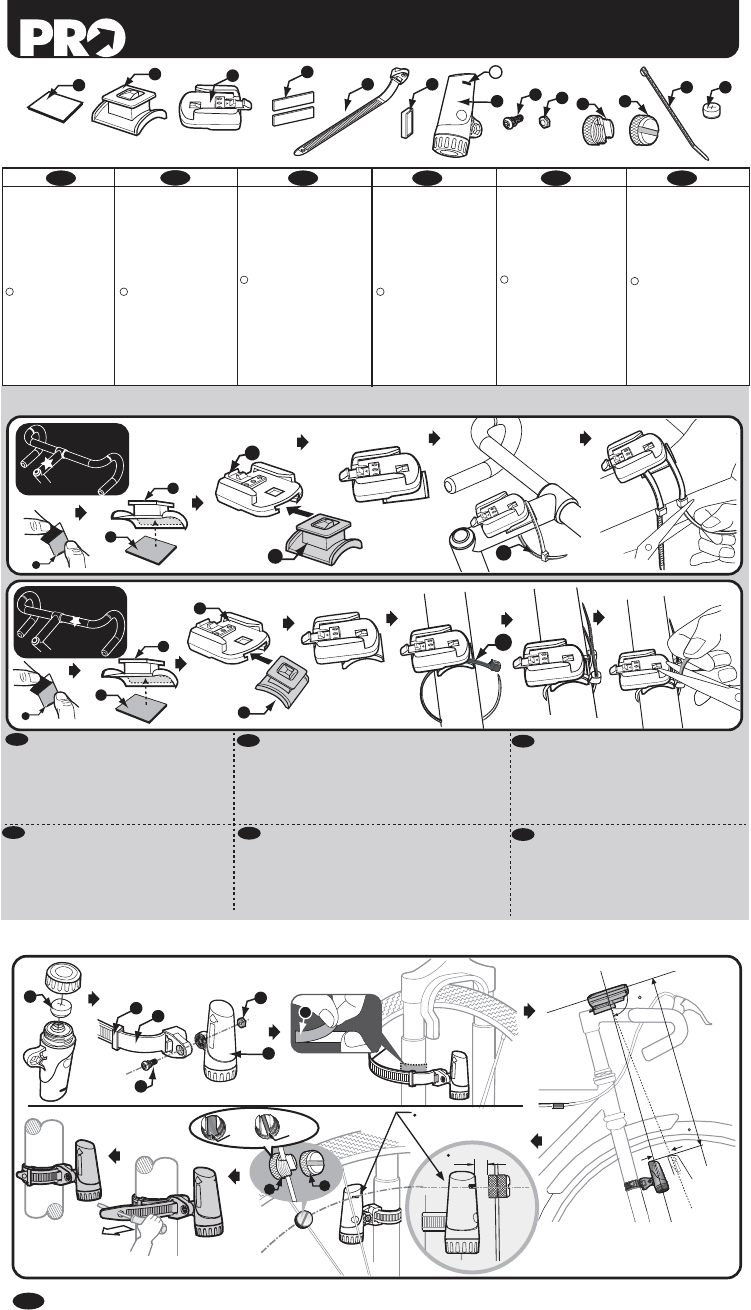
B). BRACKET MOUNTING
1.Twin adhesive
(Tape)
2. Bracket base
3. Bracket
4. Rubber pad
5. Sensor band
6. Band carrier
7. Transmitter
S. Sensor point
8. Screw
9. Nut
10. Magnet
11.Magnet cap (Screw)
12.Cable ties (L)(S)
13.1.5v battery (lr44 is
typical)
1.(Nastro) adesivo
a doppia faccia
2. Supporto staffa
3. Staffa
4. Guarnizione in gomma
5. Fascetta sensore
6. Portafascetta
7. Trasmettitore
S. Punto di rilevazione
8. Vite
9. Dado
10. Magnet
11. Coprimagnete (vite)
12. Fascette (L)(S)
13. Batteria da 1.5 V
(LR44)
1.Doppelseitiges Klebeband
2. Halterbasis
3. Halter
4. Gummimatte
5. Sensorband
6. Bandträger
7. Übermittler
S. Sensorpunkt
8. Schraube
9. Mutter
10. Magnet
11. Magnetischer
Verschlussstopfen
(Schraube)
12.Kabelbefestigung(L)(S)
13.1.5 V Batterie (LR44)
1.Adhésif double-
face (bande)
2. Base de support
3. Fixation
4. Patin de caoutchouc
5. Bande de capteur
6. Transporteur de bande
7. Transmetteur
S. Point de capture
8. Vis
9. Écrou
10. Aimant
11.
Bouchon d’aimant (vis)
12.
Attaches de fil (L)(S)
13. Pile1.5 v
(habituellement LR44)
1. Adhesivo doble (cinta)
2. Base del soporte
3. Soporte
4. Almohadilla de Goma
5. Banda del Sensor
6. Portabanda
7. Transmisor
S. Punto sensor
8. Tornillo
9. Tuerca
10. Imán
11.Cubierta del imán
(Tornillo)
12.Unión para cables(L)(S)
13.1.5V Pila
(LR44 es tipico)
1. Dubbelzijdige tape
2. Beugelbasis
3. Beugel
4. Rubberen Strip
5. Sensorband
6. Banddrager
7. Zender
S. Sensorpunt
8. Schroef (M4X12) X2
9. Moer (M4) X3
10. Magneet
11. Magneetkap (schroef)
12. Kabelbinders(L)(S)
13. 1.5V Batterij
(Meestallr44)
12
(L)
90
L< 45cm
+15
Magnet center aligns to
the marking line.
Gap < 5mm(0.2")
10
4
5
6
7
13
8
9
11
ok!
C). SPEED SENSOR INST
1. Bracket(3) could be installed either on stem(A) or
on handlebar(B) by a 90° variation of the bracket
base(2).
2. Cable tie should be well cutted and hidden to
avoid any injury when sliding on the main unit.
1.La staffa(3) può essere montata sull'asta (A) o sul
manubrio (B) modificando di 90° la posizione
dell'apposito supporto staffa(2).
2.Il cavo va accuratamente accorciato e riposto per
evitare qualsiasi ferita quando si inserisce l'unità
principale.
1.Der Halter(3) kann entweder an der Lenkstange (A) oder
an der Griffstange (B) bis zu einem 90°-Winkel zur
Halterbasis montiert werden(2).
2.Achten Sie darauf, dass die Kabelbinden säuberlich
abgeschnitten und entsprechend kaschiert sind, um
Verletzungen beim Einschieben des Computers auf den
Halter zu vermeiden.
1.Le support(3) peut être installé soit sur un rayon (A), soit
sur le guidon (B) en faisant pivoter de 90 º la base de
support(2).
2.Les attaches de câble doivent être soigneusement
coupées et cachées pour éviter toute blessure lors de
l’insertion de l’unité principale.
EN
IT
DE
FR
ES
NL
1.El soporte(3) puede instalarse en el vástago
(A) o en el manillar (B) girando 90° la base del
soporte(2).
2.Los sujetacables deberían cortarse y
esconderse bien para evitar cualquier tipo de
daño al introducir la unidad principal.
1.De beugel(3) moet worden geïnstalleerd op het
ventiel (A) of het stuur (B) door de beugelbasis
90° te draaien(2).
2.De kabelbinder moet goed zijn afgesneden en
verborgen, om verwondingen te voorkomen
als u de hoofdeenheid op de fiets schuift.
For
Flat
Spoke
For
Round
Spoke
WIRELESS COMPUTER
INST
SENSOR AND MAGNET MOUNTING
1.Install the sensor and the sensor band with the screw .
2.Mount the band carrier onto sensor band.
3.Mounting the sensor unit on the right front fork with rubber pad.
4.Mount the magnet on one spoke of the front wheel and let the
magnet face the sensor’s point. Place the ring around the
magnet to enhance the reliability of the fixed screw.
5.Adjust the relative position between the main unit and the
sensor, according to the following key points:
a). It will receive a stronger wireless signal if the sensor is more
close to the main unit.
The arrow of the sensor must point to the main unit, and
install the sensor as close to the main unit as possible and
within 45 cm (1.5 feet) to get a better wireless performance.
It is workable when the arrow symbol is down , but keeping
the arrow up is better because its sensing distance is shorter
than with the arrow down.
b). Adjust the installation angle of the sensor to aim at the
direction of the main unit within +/- 15°, the best
performances is at vertical direction (90°) between the
sensor’s arrow and the battery cap of the main unit.
c).Adjust the magnet fixed position to let the center of the
magnet align to the sensor’s point.
d).Adjust the sensor to let the gap between the magnet and the
sensor’s point is about 5mm (0.2").
6.Refer to the TEST section to testing the installation before
tighten the sensor band with a screwdriver.
7.Fix the excess sensor band by thrusting it into the band carrier.
8.Fix all parts and get ready for riding.
TEST
1.The main unit has a "Slide On/Off Detecting Switch" (patents
pending) to turn ON/OFF the power of the wireless receiver. It
can receive the wireless wheel signal only after the main unit is
slid onto the bracket.
2. Spin the front wheel to check if installation is correct. Installation
is correct if the main unit flickers "WIRELESS* " symbol. It is an
incorrect installation if there is no symbol of "wireless* symbol".
Please check the relative position among the main unit, the
sensor and the magnet, or refer to the trouble-shooting table.
*
"WIRELESS* " symbol could be varied by different model.
C. THE WIRELESS SYSTEM AND PERFORMANCES
1. The sensor transits the wheel rotating signal to the receiver in
the main unit by the wireless transmission. T
receiver from interfering by other wireless noises and causing
the main unit to display false data, install the transmitter
according to the following key points to get better performance.
a). The receiver is designed to receive a signal with only a
certain direction and angle to reduce the noise interference
from other sources. Adjust the installation angle of transmitter
to aim at the direction to the main unit within a +/- 15° angle,
the best performance is at a vertical direction.
b). The receiver will receive a stronger wireless signal if the
transmitter is more close to the receiver.
signal not only has better noise immunity
the transmitter battery’s operating life. For good wireless
performance, please install the transmitter as close to the
main unit as possible and within 45 cm (1.5 feet).
2. Precaution
This computer has almost no cross-talking interference when 2
bicycles carrying the same or similar wireless cycle computers
are ridden side by side, as long as the cross-distance is over
40cm (15.8”).
3. This computer has a “Slide On/Off Detecting Switch” to check
the main unit to slide on/off from the bracket.
a). T
increase the battery operation life, but also to delete all
indoor electromagnetic interference from electrical
equipment (such as PC monitors, handy -phones, etc.). It
will turn off the power supply of the receiver when the main
unit takes off from the bracket.
b). The main unit can only receive the wheel signal after it is slid
onto the bracket.
EN
C-a.
C-b.