TEST / PAIRING
SELECT
+Hr
SET
iOnce paired please close the
boiler control panel
The LED will start flashing red.
TEST / PAIRING
+Hr
SELECT SET
RXBC605 Installation
RXBC605 Wiring T
RXBC605
1
3
6
2
5
4
Remove the front panel from the boiler.
Do not remove boiler loop.
Replace the front panel ensuring a good seal is made.
Connect the electrical plug.
Pull out the mechanical timer.
Push fit boiler control into housing.
7Power up the boiler and check the correct operation.
Quick Guide
RT510BC+
Always isolate the AC Mains supply before installing or working on any components
that require 230 VAC 50Hz supply.
RT510BC+ (Thermostat) Button Functions
Introduction
The RT510BC+ thermosta
with the time and temperatur
boiler control
plate usually supplied with the boiler. Installing the RF boiler control takes minutes. Once
installed, you will benefit from all the control features of the RT510BC+ thermostat.
868.0-868.6MHz; <13dBm
Safety Information
Use in accor
your device befor
installation must comply with the guidance, standar
state where the pr
Product Complianc
This product complies with the essential rEMC
2014/30/EU, L
available on www.saluslegal
+Hr
SELECT
SELECT
SET
SET
+
+
+
Key Function
1. Press once t
2. Press for 3 seconds in or
Press once t
Press once t
Increase button
Decrease button
Select the clock or programme settings
Press to c
1. Press once t
2. Press for 3 seconds t
Press the buttons for 3 sec
Press the buttons for 3 sec
Box content
Quick Guide 2 x AA Alkaline
Batteries 2 x Fixing Scr
RT510BC+ Desk Stand
TEST / P AIRING
SELEC T
+H r
SE T
i O nc e pair ed please close the
boiler c on tr ol panel .
The LED will start flashing red.
TEST / P AIRING
+H r
SELEC T SE T
R XBC605 Installa tion
R XBC605 W iring T erminals
R XBC605
1
3
6
2
5
4
Remove the front panel from the boiler.
Do not remove boiler loop.
Replace the front panel ensuring a good seal is made.
Connect the electrical plug.
Pull out the mechanical timer.
Push fit boiler control into housing.
7 Power up the boiler and check the correct operation.
Quick Guide
RT510BC
Always isolate the AC Mains supply before installing or working on any components
that require 230 VAC 50Hz supply.
RT510TX Button Functions
Intr oduc tion
T he R T510T X thermosta t will swit ch y our hea ting syst em on or o , as needed , in ac c or danc e
with the time and t emper a tur e set b y y ou . It c an be used with the R XBC605 in t egr al plug-in RF
boiler c on tr ol . The RF boiler control is a direct replacement for the basic time clock or blanking
plate usually supplied with the boiler. Installing the RF boiler control takes minutes. Once
installed, you will benefit from all the control features of the RT510TX thermostat.
868.0-868.6MH z; <13dB m
S af et y I nf orma tion
U se in ac c or danc e with the r egula tions . Indoor use only . K eep y our devic e c omplet ely dr y . D isc onnec t
y our devic e bef or e cleaning it with a dr y cloth. T his ac c essor y must be tt ed b y a c ompet en t person, and
installa tion must c omply with the guidanc e , standar ds and r egula tions applic able t o the cit y , c oun tr y or
sta t e wher e the pr oduc t is installed . F ailur e t o c omply with the r elev an t standar ds c ould lead t o pr osec ution.
P r o duc t C omplianc e
T his pr oduc t c omplies with the essen tial r equir emen ts and other r elev an t pr o visions of the f ollo wing EU D ir ec tiv es: EMC
2014/30/EU , L VD 2014/35/EU , RED 2014/53/EU and RoHS 2011/65/EU . F ull t e x t of the EU D eclar a tion of C onf ormit y is
a v ailable on w w w .saluslegal .c om
+H r
SELEC T
SELEC T
SE T
SE T
+
+
+
K ey F unc tion
1. P r ess onc e t o ac tiv a t e F r ost Mode
2. P r ess f or 3 sec onds in or der t o ac tiv a t e H olida y Mode
P r ess onc e t o ac tiv a t e/deac tiv a t e B oost func tion
P r ess onc e t o en t er/e xit P ermanen t O v erride func tion
Incr ease butt on
D ecr ease butt on
S elec t the clock or pr ogr amme settings
P r ess t o c onrm y our settings
1. P r ess onc e t o en t er/e xit in T est Mode
2. P r ess f or 3 sec onds t o en t er/e xit P airing Mode
P r ess the butt ons f or 3 sec onds t o en t er Installer Mode
P r ess the butt ons f or 3 sec onds t o en t er C lock S ettings
Bo x cont ent
Q uick G uide 2 x AA A lk aline
B a tt eries 2 x F ixing S cr ews
R T510T X D esk S tand
R T510T X D ip S wit ch S ettings
T he DIP S wit ches c an be f ound on the r ear of y our thermosta t .
C on tr ol f ea tur e TPI S pan
O per a tion W hen TPI is selec t ed on DIP
swit ch № 2, the DIP swit ch
№ 1 is func tional . Y ou c an
choose the C y cles P er H our
bet w een a lo w er c omf or t
lev el (6CPH) and a higher
c omf or t lev el (9CPH).
W hen S pan is selec t ed
on DIP swit ch № 2,
the DIP swit ch № 1 is
not func tional . T he
t emper a tur e ac c ur ac y of
y our thermosta t is set t o
± 0.25 °C.
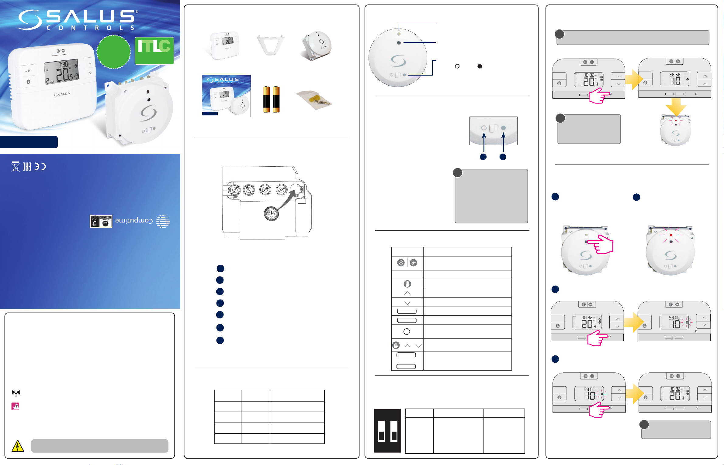
TEST / P AIRING
SELEC T
+H r
SE T
TEST / P AIRING
SELEC T
+H r
SE T
3 S ec
TEST / P AIRING
+H r
SELEC T SE T
3
4
T est the P airing Pr ocess
P airing Pr ocess
Once the LED stops flashing, press the
TEST / PAIRING button for 3 sec.
1 2
B eg in the pairing pr oc ess
End the pairing pr oc ess
i
i
i
D uring t est pairing , boiler c on tr ol should ash c onrming pair . If not , please f ollo w
P airing P r oc ess .
W hen en t er t est pairing
mode , af t er a 10 minut e
c oun t do wn the thermosta t
will time out .
T erminal I den tier D escription
1 N N eutr al
2 L Liv e input (230V A C )
3 CO M C ommon t erminal (v olt fr ee)
4 N.O . N ormally O pen
R XBC605 U ser C ontr ols
R XBC605 S wit ch P osition
LED - It will be on when the thermostat is demanding
heat.
Mode Switch
The AUTO / MANUAL switch allows you to turn on the
Boiler Control manually if required.
SYNC Button - This is used only for pairing the RF
communications.
P r ess the SYNC butt on f or 3
sec onds un til LED star ts ashing .
T he L G+5V is r eady t o be pair ed
with y our thermosta t .
3 S ec
2. MANUAL mode. The user
can also move the switch to the
MANUAL position; when in this
mode, the boiler will be always turned
on and the LED indicator will also
be lit constantly. The manual mode
i s o n l y t o b e u s e d a s a t e m p o r a r y
control if problems develop with the
communication from the thermostat.
1. AUTO mode. When the switch
on the Boiler Control is in the AUTO
(normal) position, the Boiler Control
will automatically receive the RF signal
from the transmitter and control the
boiler based on the programming of
the transmitter. 1 2
When the thermostat is operating in
NORMAL mode, if the Boiler Control has
not received a signal from the transmitter
after 1 hour, the Boiler Control will turn
off the boiler, and the LED indicator will
fl as h c onstantly ( two ti me s e ver y s ec on d).
Once the Boiler Control receives a valid
ON or OFF signal, the Boiler Control will
control the heating system accordingly.
SAL US C ontr ols plc
SAL US House
D odw or th Business P ar k S outh,
Whinb y R oad , D odw or th,
Bar nsle y S75 3SP , UK .
T : +44 (0) 1226 323961
E: sales@salus-t ech.com
E: t echsuppor t@salus-t ech.com
SAL US C ontr ols is a member of the C omputime Gr oup .
M aintaining a polic y of continuous pr oduc t de v elopment SAL US C ontr ols plc r eser v e the r ight t o
change specification, desig n and mat er ials of pr oduc ts list ed in this br ochur e without pr ior notic e.
w w w .salus-t ech.c om
Issue Da t e: F ebruar y 2018
V005
F or PDF I nstalla tion guide please go t o w w w .salus-manuals .c om
TEST / P AIRING
SELEC T
+H r
SE T
3 S ec
RT510BC+ (Thermostat) Dip Switch Settings
TEST / PAIRING
SELECT
+Hr
SET
TEST / PAIRING
SELECT
+Hr
SE T
3 Sec
TEST / PAIRING
+Hr
SELECT SE T
3
4
T
Pairing Process
Once the LED stops flashing, press the
TEST / PAIRING button for 3 sec.
12
Begin the pairing process
End the pairing process
i
i
i
During test pairing, boiler c
Pairing P
When enter t
mode, after a 10 minute
countdown the thermosta
will time out.
T Identier Description
1 N Neutral
2 L Live input (230V A
3COM Common terminal (volt fr
4 N.O Normally Open
RXBC605 User Controls
RXBC605 Switch P
LED - It will be on when the thermostat is demanding
heat.
Mode Switch
The AUTO / MANUAL switch allows you to turn on the
Boiler Control manually if required.
SYNC Button - This is used only for pairing the RF
communications.
Press the SYNC butt
seconds until LED starts ashing.
The L
with your thermostat
3 Sec
2. MANUAL mode. The user
can also move the switch to the
MANUAL position; when in this
mode, the boiler will be always turned
on and the LED indicator will also
be lit constantly. The manual mode
is only to be used as a temporary
control if problems develop with the
communication from the thermostat.
1. AUTO mode. When the switch
on the Boiler Control is in the AUTO
(normal) position, the Boiler Control
will automatically receive the RF signal
from the transmitter and control the
boiler based on the programming of
the transmitter. 1 2
When the thermostat is operating in
NORMAL mode, if the Boiler Control has
not received a signal from the transmitter
after 1 hour, the Boiler Control will turn
off the boiler, and the LED indicator will
flash constantly (two times every second).
Once the Boiler Control receives a valid
ON or OFF signal, the Boiler Control will
control the heating system accordingly.
SAL
SAL
Dodworth Business Park South,
Whinby Road, Dodworth,
Barnsley S75 3SP
T: +44 (0) 1226 323961
E: sales@salus-tech.com
E: techsupport@salus-tech.com
SAL
Maintaining a policy of continuous product development SALUS Controls plc r
change specification, design and materials of products listed in this brochure without prior notice.
ww
Issue Date: February 2018
V007
For PDF Installation guide please go to www
TEST / PAIRING
SELECT
+Hr
SE T
3 Sec
Boiler
PLUS
C
O
M
P
L
I
A
N
T
Internal T
Load Compensation
The DIP Swit
boiler receiv
NA SP
RAD ITLC
Contr ITL SP
Operation ITL
Load C
improv
When Span is selected
on DIP switch № 2, the
DIP switch № 1 is not
functional.