Floor Heating Controller
Status April 2002
For the regulation of thermal storage floor heating systems
with heating mats.
Operating and
installation instructions
The controller base type 5TC9 203 is
adaptable to the following switching
programs:
DELTA plus
DELTA profil**
DELTA style
DELTA i-system*
(DELTA-vita, DELTA-line)
1. Functional description:
The floor heating controller consists of two parts:
control device for setting the required floor heating tempera-
ture,
remote sensor in the floor for monitoring the set temperature.
1.1. Control device:
The required floor temperature can be set with the control
knob. The number scale
d
- 5 on the knob corresponds to a
temperature range of 10 - 50°C. Please note the setting in-
structions of the manufacturer of your floor heating. If the set
floor heating temperature is not reached, heat is requested by
the control device and this state is indicated by the red LED
located above the control knob.
The control knob can also be used to limit the temperature ad-
justment range (item 7).The floor heating can be switched on
and off with the 0/I mains switch.
A temperature reduction can also be programmed via an ex-
ternal timer, e.g.for off-peak operation at night. If your system
is provided with a timer, the start of the temperature reduction
is indicated by the green LED located above the control knob.
The temperature reduction is about 5°C.
1.2. Sensor
The sensor is installed in the floor.It monitors the floor tempe-
rature set at the control device and gives the command to
switch the floor heating system on and off.
4.2. Remote sensor
Sensing element NTC
Sensor cable PVC, 2 x 0,50 mm
2
, 4m
Degree of protection
according to DIN VDE 0470T1 IP 68
Environment temperature –25 ... +70
The sensor cable can be extended up to 50 m with a two-core
cable with a cross-section of 1.5 mm
2
without influencing the
accuracy of the controller. If the sensor cable is laid in a cable
channel or near to a high tension line, a shielded cable has to
be used.
Sensor characteristics: Measuring instrument R
i
> 1 MΩ
Temp. Resistance Temp. Resistance
°C kΩ °C kΩ
5 4,527 30 1,655
10 3,657 35 1,379
15 2,974 40 1,151
20 2,432 45 0,968
25 2,000 50 0,816
NOTICE!
This device must only be installed or fitted by a quali-
fied specialist. The applicable safety rules and regulati-
ons of VDE and the local electricity supply companies
must be observed. In order to achieve protection class
II, specific mounting procedures have to be followed
accordingly. The controller complies with the require-
ments of DIN EN 60730, type 1 and is radio-interferen-
ce-suppressed according to VDE 0875 and EN 55014.
2. Installation
Mounting the controller requires the appropriate frame of
the switching program DELTA with special controller relief.
2.1. Sensor:
The sensor must be installed in a protective tube, so that it is
protected from moisture and easy to replace in case of repair.
2.2. Mounting in recessed wall box 55 mm (DIN 49 073):
a) Electrical connection:
According to circuit diagram; solid conductor - 1 to 2.5
mm
2
rated cross-section. No protective conductor is ne-
cessary. The protective conductor terminal only serves
for looping-in.The class of protection II can be achieved
by means of appropriate installation measures.
b) Mount controller on box by means of thread-forming
flush-type box screw.
2.3. Assembly of colour set and switch frame
a) Remove protection cap.
b) Attach rocker of switch
c) Mount the cover with switch frame. Engage the top left of
cover in the base and insert screw. Push on the adjust-
ment knob.
3. Information for the installer
– The 0/I switch on the control device disconnects the device
in one pole from the mains supply and interrupts the circuit
to the heating resistor in the floor.
– When working on the load circuit, the system voltage must
be disconnected (e.g.switch off fuse).
– With sensor open-circuit, the relay contact is closed; with
sensor short-circuit, the relay contact is open.
–NOTICE! In case of failure mains supply might be on sen-
sor cable.
4.Technical data
4.1. Control device
Operating voltage 1/N/AC 230 V 50 Hz
Tolerance range 195 .... 253 V AC, 50 Hz
Temp. adjustment range (Number scale)
d
.... 5 (10... 50°C)
Switching current 10 A at cos γ=1
Switching capacity 2,3 kW
Switch Mains “On/Off”
Red LED display Control device request heat
Green LED display Temperature reduction “On”
Contact (relay) 1 NO contact
Temp.reduction (TA) About 5 K
Switching temp. difference About 1 K
Degree of protection of housing
according to EN 60529 IP 30
Environment temperature T40
Storage temperature –25°C…70°C
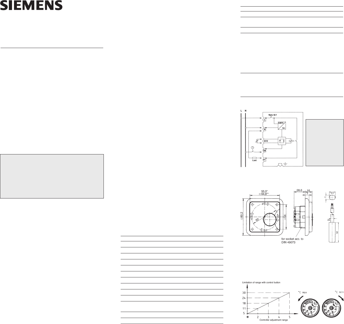
7. Limitation of temperature adjustment
range
The controller is set at the works to the maximum adjustment
range from
d
to 5.
The control knob has two setting rings. For range limitation,
see the diagram below.
5. Block diagram
Note:
For activating the
temperature
reduction, the
terminal TA
needs to be
switched to the
neutral conductor.
6. Dimension drawing
Remote
Controller sensor
Errors possible – subject to alterations