729701
1
Zoom out
Zoom in
Vorherige Seite
1/2
Nächste Seite
5V Versorgungsspannung an. Die LED Ladekontrolle zeigt den
Ladezustand an.
Ladekontrolle Bedeutung
LED rot Akku wird aufgeladen
LED grün Akku ist vollgeladen.
5.1 Einlegen des Akku
Önen Sie die Abdeckung wie in
der Abbildung gezeigt.
Legen Sie den Akku in das
Gerät ein.
Schließen Sie die Abdeckung,
wie in der Abbildung gezeigt.
1. Product layout
OPERATING MANUAL
SCENE CONTROLLER
HKZW-SCN04-V1.0
The Scene Controller is a slave product that is wireless, portable and
rechargeable . It can control a Z-Wave device, such as smart plug, smart
dimmer through a Z-Wave gateway. You can also activate a scene like
sleep scene, movie scene and entertainment scene with it.
The features list:
(1) Z-Wave Plus certified for wide compatibility (500 serials product).
(2) Support remote control anywhere and anytime.
(3) Scene Controller is capable of sending four different scene commands
with four buttons.
(4) The battery is rechargeable.
(5) The battery will run for half a year per single charging.
(6) Support low battery alarm with a buzzer.
(7) Support communication failure alarm with a buzzer.
(8) Support firmware OTA.
. GENERAL INFORMATION ABOUT SCENE CONTROLLER
Radio protocol:
Radio frequency:
868.42MHz (EU) 908.42MHz (US)
921.42MHz (AU)
Range:
Dimensions
50*50*16mm
36mA
3uA
Power supply:
2. Specifications
Single LIR2450 3.6V Battery
Storage environment:
Operational temperature:
More than 100m outdoors
About 30m indoors (depending
on building materials)
Working current:
Standby current:
-10~50 0%~85%
0~40
Z-Wave
LED
LED
Micro USB port
Ⅱ.INSTALLATION
Open the cover:
Open the cover, as the figure below shows.
Insert your battery:
Insert your battery and close the cover, as the figure below shows.
. Z-WAVE NETWORK INCLUSION
Scene Controller can be included and operated in any Z-Wave
network with other Z-Wave certified devices from other
manufacturers and/or other applications. All non-battery operated
nodes within the network will act as repeaters regardless of vendor
to increase reliability of the network.
Included as a non-secure device
(1) Insert the LIR2450 battery.
(2) Set the Z-Wave network main controller into learning mode
(see Z-Wave network controller operating manual)
.
(3) Triple click the Z-button.
(4) If the inclusion is successful, the LED will blink in blue less than
for 5 seconds and then keep on for 15 seconds.
TIP:
If you want your Scene Controller to be a security device that
use secure/encrypted message to communicate in a Z-Wave
network, then a security enabled Z-Wave controller is needed.
To remove the Scene Controller from the Z-Wave network:
(1) Insert the LIR2450 battery.
(2) Set the Z-Wave network main controller into learning mode
(see Z-Wave controller operating manual).
(3) Triple click the Z-button, if the exclusion is successful, LED will blink
in orange for less than 5 seconds and then keep on for 3 seconds.
Ⅳ. REMOVING FROM Z-WAVE NETWORK
Ⅴ. RESET SCENE CONTROLLER
Reset procedure clears the Scene Controller's memory, including
Z-Wave network information.
To reset Scene Controller:
Pressing and holding the Z-button for 20 seconds. Release the button
after 20 seconds, LED will keep in yellow for 3 seconds. Scene
Controller will be reset to factory defaults if you short press the
button within this 3 seconds.
Ⅵ. LOW BATTERY ALARM FUNCTION
Scene Controller will send battery report to the lifeline group when
Z-Button is triggered during the sleep mode. If the battery level of
the Scene Controller is less than 20%, the Scene Controller will beep
3 times when the button is pressed.
. COMMUNICATION FAILURE ALARM FUNCTION
The Scene Controller will beep one time when the communication
between the Scene Controller and any one of the controlled device
is failed.
. TESTING Z-WAVE NETWORK RANGE
Scene Controller's LED indicator can signal its communication quality
with the Z-Wave main controller.
To start testing:
Press and hold the Z-button for 11 to 15 seconds, the LED will keep on
in purple for 3 seconds, it will enter testing mode if you short press the
Z-button during these 3 seconds.
Blink in green –Scene Controller establish a direct communication with
the main controller, and still under checking.
Keep green – The green light should last about 2 seconds, which means
the direct communication is stable.
Blink in orange –Scene Controller can communicate with the main
controller in intermediate radio transmit power level, and still under
checking.
Keep orange – The communication quality is moderate.
Keep Red – The communication is failed.
TIP:
1. This function works only when Scene Controller
has been included into a Z-Wave network.
2. Click the Z button to exit the test.
. BATTERY CHARGING
Scene Controller has an internal rechargeable battery that will run for
half a year under the normal use condition. If the battery level is less
than 20%, this will activate the low battery level function, this means
you need to charge the battery.
The charger's output should be a micro USB terminal with the
specification of output DC 5V.
The LED nearby the micro USB port will keep on in red during the
changing, and it will turn to green if the charging is finished.
Ⅹ. ASSOCIATION
Association allows the Scene Controller to control another Z-Wave
device directly, such as Smart Switch, Smart Dimmer, etc.
Scene Controller supports nine association groupings, every group
relates to a specific button action. View details in the follow
section of “. BUTTON FUNCTION”.
Group 1 allows Scene Controller sends central scene notification
command and battery report command when any button is triggered.
Details shown as the below diagram 1.
Group 2 allows Scene Controller sends basic set command when the
button 1 is triggered.
Group 3 allows Scene Controller sends switch multilevel set, multilevel
start level change and multilevel stop level change command when the
button 1 is triggered.
Group 4 allows Scene Controller sends basic set command when the
button 2 is triggered.
Group 5 allows Scene Controller sends switch multilevel set, multilevel
start level change and multilevel stop level change command when the
button 2 is triggered.
Group 6 allows Scene Controller sends basic set command when the
button 3 is triggered.
Group 7 allows Scene Controller sends switch multilevel set, multilevel
start level change and multilevel stop level change command when the
button 3 is triggered.
Group 8 allows Scene Controller sends basic set command when the
button 4 is triggered.
Group 9 allows Scene Controller sends switch multilevel set, multilevel
start level change and multilevel stop level change command when the
button 4 is triggered.
Details shown as the below diagram 2
Included as a secure device
(1) Insert the LIR2450 battery.
(2) Set the Z-Wave network main controller into learning mode
(see Z-Wave network controller operating manual).
(3) Pressing and holding the Z-button for 3 seconds.
(4) If the inclusion is successful, the LED will blink in green less than
for 5 seconds and then keep on for 15 seconds.
NOTE:
Use this procedure only in the event that the network
primary controller is missing or otherwise inoperable.
means Button 1 means Button 2
means Button 3 means Button 4
Button ID
Scene Number
1
1
2
2
3
3
4
4
Button ID
Any button
Group ID
1
Action & notification
Press: Central scene notification
( Key Attributes=0)
Hold: Central scene notification
( Key Attributes=2)
Release: Central scene notification
( Key Attributes=1)
Diagram 2:
Button 1 2 Press: Basic Set Hold: Reserve
Release: Reserve
3
Press: Switch multilevel set
Hold: Multilevel start level change
Release: Multilevel stop level change
Button 2 4 Press: Basic Set Hold: Reserve
Release: Reserve
5
Press: Switch multilevel set
Hold: Multilevel start level change
Release: Multilevel stop level change
Button 3 6 Press: Basic Set Hold: Reserve
Release: Reserve
7
Press: Switch multilevel set
Hold: Multilevel start level change
Release: Multilevel stop level change
Button 4 8 Press: Basic Set Hold: Reserve
Release: Reserve
9
Press: Switch multilevel set
Hold: Multilevel start level change
Release: Multilevel stop level change
TIP:
1. The max number of associated nodes of all these
9 groups is 5.
2. Association allows for direct transmission of control
command between devices and takes place without the
participation of the main controller.
Ⅺ. WAKE UP
Wake up interval:
Available settings: 0
Default setting: 0
Pressing and holding Z-Button for 3 seconds. Led will turn to green,
which means Scene Controller has successfully sent the wake up
notification out.
NOTE:
The interval time must be set to 0. The wake up
notification will not wake the Scene Controller, only the
action of the button can you wake the Scene Controller.
. BUTTON FUNCTION
Scene Controller offers three button action types, including short
press, held down and release.
Short press allows Scene Controller sends:
Central scene notification command to the associated nodes,
Basic set command to the associated nodes.
Switch multilevel set command to the associated nodes.
Held down (more than 1 second less than 20 seconds) allows Scene
Controller sends:
Central scene notification command to the associated nodes,
Multilevel start level change command to the associated nodes.
Release allows Scene Controller sends:
Central scene notification command to the associated nodes,
Multilevel stop level change command to the associated nodes.
XIII. ADVANCED CONFIGURATION
Scene Controller offers a wide variety of advanced configuration
settings. Below parameters can be accessed from main controllers
configuration interface.
Parameter No.254 Enable/disable the configuration command
Lock/unlock all configuration parameters.
0 – Unlock.
1 – Lock.
Default setting: 0
Parameter size: 1[byte]
Parameter No.255 Reset Scene Controller
Reset the sensor or remove from the Z-Wave network
Value: 1431655765
Default: 1
Parameter size: 4[byte]
Reset to factory default settings and removed from the Z-Wave network.
Value: 85
Default: 1
Parameter size: 1[byte]
Reset the values of the configuration command to default setting.
You may need the Over the Air (OTA) feature for the product's
firmware upgrade. Your Scene Controller can not be used after OTA.
In such a case, you need to activate the product by pressing and
holding the Z-Button until the led turns on, this procedure may take
you about 10 seconds. After these your Scene Controller will be usable.
XIV. NOTES FOR OTA
Diagram 1:
+
1 Funktion und Verwendung
Der Szenenschalter 1 ist eine kabellose, tragbare und wieder-
aufladbare Fernbedienung. In Verbindung mit einer SmartHome
Zentrale kann er ein Z-Wave-Gerät steuern, wie z.B. Zwischen-
stecker 3. Sie können mit ihm auch eine Szene wie Schlafszene,
Filmszene und Unterhaltungsszene aktivieren..
2 Allgemeine Sicherheitshinweise
Lesen Sie Bedienungsanleitung vor Inbetriebnahme des
Gerätes vollständig durch.
Das Gerät ist für die Verwendung in Gebäuden vorgesehen.
Betreiben Sie das Gerät nur in trockenen Innenräumen.
Vermeiden Sie den Einfluss von Feuchtigkeit, Staub sowie
Sonnen- oder andere Wärmebestrahlung.
Verwenden Sie nur den vorgegebenen Baerietyp / Akku!
Akku nicht kurzschließen oder auseinander nehmen Ex-
plosionsgefahr!
Akkus können bei unsachgemäßem Umgang beschädigt
werden, Feuer fangen und explodieren. Es besteht Ex-
plosionsgefahr, wenn die Akkus durch einen falschen Typ
ersetzt werden. Beschädigte Akkus setzen stark ätzende
Stoe frei oder können explosive Gemische bilden. Dies
führt zu möglichen Gesundheitsschäden, Schädigung der
Lu- und Atemwege, Hautschäden, Schädigung der Augen
und sonstigen Verletzungen. Im Falle eines Brandes können
giige Stoe (Gase, Flüssigkeiten usw.) aus dem Gerät und
dem Akku entweichen, die schwere Gesundheitsschäden
verursachen können.
Betreiben Sie das Gerät nicht weiter, wenn es selbst und/
oder der Akku oensichtliche Beschädigungen aufweist.
Kurzanleitung
Szenenschalter 1
4-Tasten-Fernbedienung/Schalter
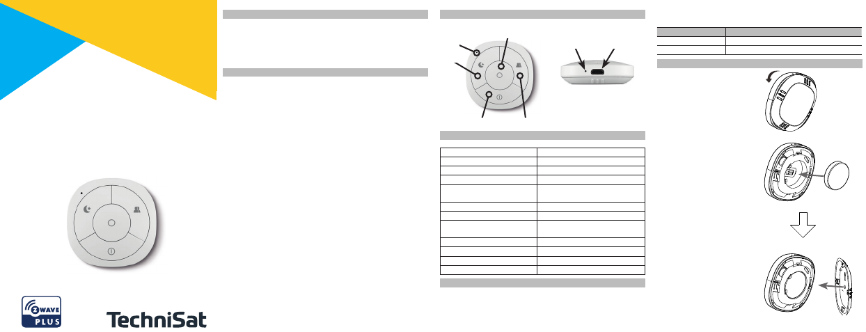
3 Bedienelemente und Anschlüsse
4 Technische Daten
Gerät Szenenschalter 1
Artikel-Nr. 0000/9521
EAN 4019588502093
Stromversorgung Akku LIR2450 3.6V
Stromverbrauch Betrieb
Standby
36 mA
3 µA
Baerielaufzeit Bis zu 6 Monate
Sendefrequenz 868,42 MHz
Funkreichweite ≤ 100 m (Freifläche)
≤ 30 m (In Gebäuden)
Schutzklasse IP20
Betriebstemperaturbereich 0°C bis 40°C
Abmessung 50 x 50 x 16 mm
Gewicht 26 g
5 Inbetriebnahmen
Der Szenenschalter 1 wird mit einer wiederaufladbaren Baerie
(Akku) betrieben. Zum Aufladen muss der Akku im Gerät
eingelegt sein. Schließen Sie den Szenenschalter über das beilie-
gende USB-Ladekabel an einen passenden USB-Anschluss mit
Taste 1 Taste 4
Taste 2
Taste 3
Lerntaste
LED
Ladekontrolle
Micro USB
Anschluss
LED
+
1

Brauchen Sie Hilfe? Stellen Sie Ihre Frage.

Forenregeln

Missbrauch melden von Frage und/oder Antwort

Libble nimmt den Missbrauch seiner Dienste sehr ernst. Wir setzen uns dafür ein, derartige Missbrauchsfälle gemäß den Gesetzen Ihres Heimatlandes zu behandeln. Wenn Sie eine Meldung übermitteln, überprüfen wir Ihre Informationen und ergreifen entsprechende Maßnahmen. Wir melden uns nur dann wieder bei Ihnen, wenn wir weitere Einzelheiten wissen müssen oder weitere Informationen für Sie haben.

Art des Missbrauchs:

Zum Beispiel antisemitische Inhalte, rassistische Inhalte oder Material, das zu einer Gewalttat führen könnte.

Beispielsweise eine Kreditkartennummer, persönliche Identifikationsnummer oder unveröffentlichte Privatadresse. Beachten Sie, dass E-Mail-Adressen und der vollständige Name nicht als private Informationen angesehen werden.

Forenregeln

Um zu sinnvolle Fragen zu kommen halten Sie sich bitte an folgende Spielregeln:

Neu registrieren

Registrieren auf E - Mails für Technisat Szenenschalter 1 wenn:


Sie erhalten eine E-Mail, um sich für eine oder beide Optionen anzumelden.


Das Handbuch wird per E-Mail gesendet. Überprüfen Sie ihre E-Mail.

Wenn Sie innerhalb von 15 Minuten keine E-Mail mit dem Handbuch erhalten haben, kann es sein, dass Sie eine falsche E-Mail-Adresse eingegeben haben oder dass Ihr ISP eine maximale Größe eingestellt hat, um E-Mails zu erhalten, die kleiner als die Größe des Handbuchs sind.

Ihre Frage wurde zu diesem Forum hinzugefügt

Möchten Sie eine E-Mail erhalten, wenn neue Antworten und Fragen veröffentlicht werden? Geben Sie bitte Ihre Email-Adresse ein.


Info