RReellaayy oouuttppuuttss::
LUXOR 402 (C1 and C2) 2 x 16(6) A, 250 V~
LUXOR 400 (C1 to C4) 4 x 16(6) A, 250 V~
LUXOR 404 (C1 to C4) 4 x 16(6) A, 250 V~
IInnffoo::
• The switching outputs to each other
and against the supply voltage
are floating.
• Any external wire/phase can be
connected!
• The switching outputs are not suitable for switching protective low voltage!
Operating Manual
LLUUXXOORR 440000
LLUUXXOORR 440022
LLUUXXOORR 440044
11..00 DDeessiiggnnaatteedd uussee
22..00 BBrriieeff ddeessccrriippttiioonn
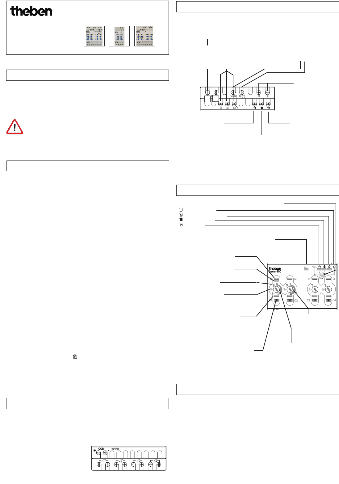
33..22 DDeessccrriippttiioonn ooff iinnppuutt tteerrmmiinnaallss
33..33 DDeessccrriippttiioonn ooff ccoonnttrrooll lleevveell
33..11 DDeessccrriippttiioonn ooff oouuttppuutt tteerrmmiinnaallss
44..00 CCoonnnneeccttiinngg tthhee uuppggrraaddee mmoodduulleess
LUXOR 400
LUXOR 402 LUXOR 404
The
LLUUXXOORR
range is suitable for installation in single and multiple family hou-
ses, offices etc.The devices control light and light with time functions. The devi-
ces are designed for installation in the distributor and/or control cabinet. They
are suitable for use in dry rooms with a normal amount of dirt.
IInn oorrddeerr ttoo pprreevveenntt aannyy ddaannggeerr ooff ffiirree oorr rriisskk ooff eelleeccttrriicc sshhoocckk,,
tthhee uunniitt mmaayy oonnllyy bbee ccoonnn
neecctteedd aanndd iinnssttaalllleedd bbyy aa qquuaalliiffiieedd
eelleeccttrriicciiaann,, iinn ccoommpplliiaannccee wwiitthh nnaattiioonnaall rreegguullaattiioonnss..
The basic device
LLUUXXOORR 440000
is mandatory in an installation where a requi-
rement exists for functions such as panic, central ON or OFF, presence simu-
lation, integration of an FI switch (RCD) or low voltage control. Without the
basic device, upgrade devices LUXOR 402 (2-channel) or LUXOR 404 (4-
channel) should be used simply as surge / switch modules with time
function.
Either key or switch can be connected to a control voltage of 230 V at
inputs I 1 to I 4.
In principle, various external wires/phases can be applied to the control in-
puts and the switching outputs.
Terminals I 4 (L) and I 4 (N) are specifically intended for use of a
FI switch (RCD) (with LUXOR 400, 404).
Terminals U are specifically intended for controlling low voltage (8-48 V
AC/DC) (with LUXOR 400).
Devices LUXOR 400, 402 and 404 feature time functions for either channel
C1 or C2.
Basic device LUXOR 400 can be upgraded with up to 15 additional devices.
Integration is via the COM interface.
Pressing a key selects and activates functions such as panic, central switch
ON, central switch OFF and presence simulation (switch only).
Panic, central switch ON and OFF keys enable all individually defined swit-
ching channels to be switched on and off at one single key.
The presence simulation function recreates daily procedures in the connec-
ted rooms. These are saved over a week and continuously updated. If the
switch connected to terminal is now pressed, (e.g. for absence, holiday
etc.), the presence simulation function starts at the defined switching out-
puts for the period of activation.
Special connection terminal I 4 (L)
+ I 4 (N) for FI connection
The terminal I 4 (N) must be con-
nected with or without FI (RCD)!
(with LUXOR 400, 404)
Universal voltage input
8 V AC/ DC to 48 V AC/ DC
(with LUXOR 400 only)
EEnnssuurree ccoorrrreecctt ppoollaarriittyy
ooff LL aanndd NN!!
Connection terminal for
‘panic’ key
(with LUXOR 400 only)
Connection terminal for
‘central OFF’ key
(with LUXOR 400 only)
Connection terminal
for ‘presence simulation’
switch
(with LUXOR 400 only)
LED (input LED) illuminates,
when a key signal is present.
LED (output LED) illuminates,
when the relay is switched on.
Manual key (channel key) for manual
ON/OFF switching and programming of
central functions
Key setting
LED illuminates when a key
signal is present at input U.
Setting the time
control from
1 min to 20 min
Setting the time control
from 1 min to 15 min
Switch setting
As long as central switch on
LLUUXXOORR 440000
is in position:
Central ON
Presence simulation
Central OFF
Panic
both the corresponding LED and
the
SSEETT
LED illuminate (also on upgrade devices)
InputsI 1, I 2, I 3, I 4
Control voltage 230 V~
Any external wire/
phase can be connected!
Operating voltage
230 V ~,
+10 %/ -15 %
310 409 06
•
•
•
•
•
•
•
•
•
•
––
++
• Use the following lines: EIB/KNX bus line type YCYM or Y(ST)Y or
telecommunication line J-Y(ST)Y.
• Connect both sides of the shielding to the minus bus terminal on the
COM bus.
• The COM line length may be up to 100 m.
• Always route the COM line separately from other lines (separate cable).
• Do not route the COM line parallel to 230 V lines.
• Upgrades to max. 16 devices inc. basic module.
• Ensure correct polarity!
-> If the COM connection fails, the SET LED flashes continuously.