Line-V
HTM511A
OWNER’S
MANUAL
Congratulations on your
purchase of this UPM line-
voltage thermostat. Please
take the time to read and
understand this manual so
you can begin to enjoy the
convenience this product
offers.
FEATURES
! Ideal for electric baseboards,
convectors and radiant
floor/ceiling heaters
! Precision temperature control
with selectable cycle rates
! Intelligent Adaptive Regulation
! Temperature display in
!
!
! Rating: 120V~240V AC, 60Hz
! MAXIMUM LOAD: 12.5A
- 3000W @ 240V or
- 1500W @ 120V
! MINIMUM LOAD: 500W
°C or °F
Quiet operation
Simple two wire installation
CAUTION!
TO AVOID FIRE, SHOCK, OR DEATH, SHUT OFF POWER SUPPL
AT THE CIRCUIT BREAKER OR FUSE AND TEST THAT THE
POWER IS OFF BEFORE WIRING.
This thermostat is compatible with most high voltage (120V to 240V AC)
electrical heaters or heating appliances. The minimum load
requirement is 500W.
This product operates at 120V to 240V AC. Do not install it unless
you are completely familiar and competent with house wiring.
Handle with caution to prevent any risk of electrical shock that
could cause serious injury or death.
Ensure that the heating system is protected by appropriate circuit
breakers or fuses.
Approximately 5ft (1.5m) from the floor.
All wiring must comply with applicable codes and regulations.
For wiring, use COPPER conductors only
Do NOT connect voltage different from device rating.
The thermostat must be fully installed in order for the buttons and LCD to operate.
This thermostat should be mounted:
INSTALLATION
OPERATING MODE SETTING
INSTALLATION
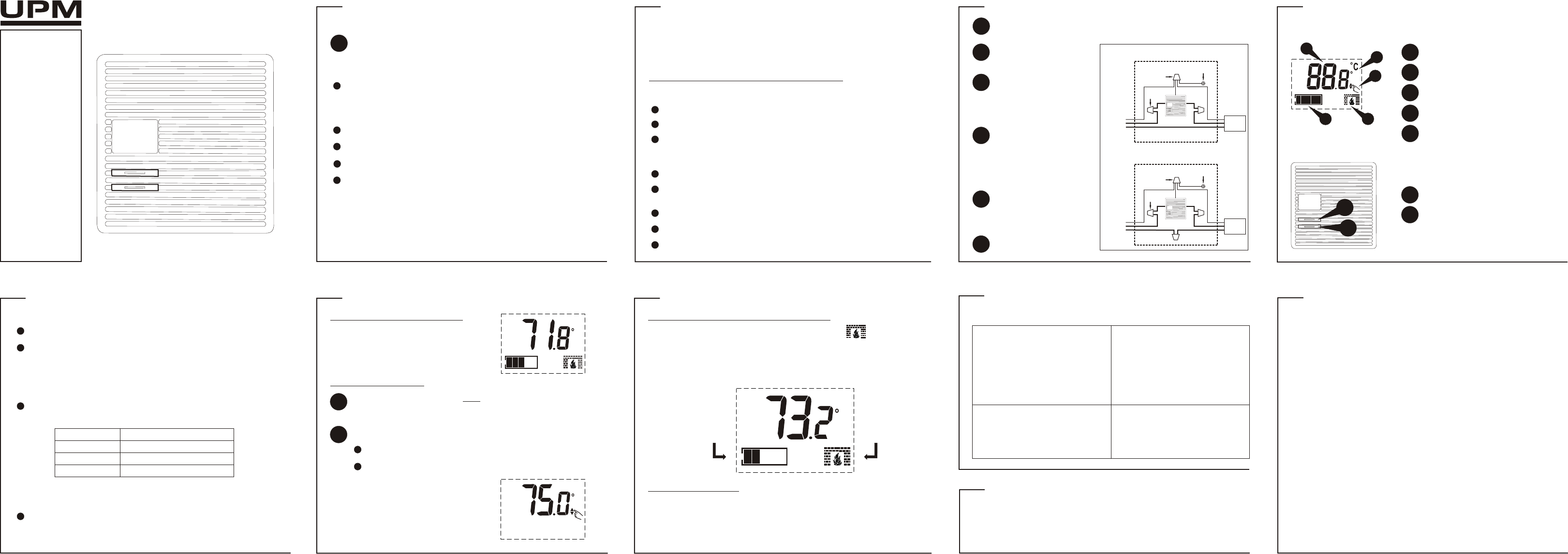
Mount the new thermostat into
the wall box using the two screws
provided through the mounting
holes. (Remove the cover if
necessary).
Using the wire nuts provided,
securely fasten each wire from
the new thermostat to a wire in
the wall box. Refer to the
diagram. NOTE: ENSURE NO
BARE WIRE IS EXPOSED.
Remove the old thermostat
carefully and identify the two
wires from the wall box.
Reconnect power supply.
DISCONNECT THE POWER SUPPLY AT THE CIRCUIT BREAKER
OR FUSE BEFORE PROCEEDING WITH THE INSTALLATION.
4-
Wire Nut
Metal Wall Box
*
*
1
2
3
4
Electric
Baseboard
Heater
120-240V AC
Line
CHOOSING A LOCATION FOR A NEW THERMOSTA
Near or in a frequently occupied room, preferably on an inside partitioning wall.
On a section of the wall without pipes or duct-work.
Near a window, on an outside wall, or next to a door leading outside.
This thermostat should NOT be mounted:
Exposed to direct light or heat from the sun, lamp, fireplace, or other heat radiating
objects which may cause false readings.
Near or in a direct airflow from supply registers and return-air grilles.
Near concealed pipes and chimneys.
In areas of poor air circulation, such as behind a door or in an alcove.
This thermostat gives you the options to:
To enterUP and DOWN buttons together.
Select the cycle rate; and/or
Select the temperature display in °C or °F
Press the UP button to select the desired CYCLE RATE.
There are 3 different cycle rates to choose from.
Press the DOWN button to toggle between the °C or °F display.
NOTE: The default temperature unit is °C
OFF (fixed span)
12 seconds
240 seconds (4 minutes)
Cr
Cr-0
Cr-1
Cr-2
CYCLE RA
In the setting mode:
OPERATION OPERATION
CURRENT TEMPERATURE DISPLAY
The current (room) temperature is
normally displayed on the LCD screen.
TEMPERATURE SETTING
Press the UP or DOWN button once to enter the temperature setting
mode. The “hand” symbol will appear
the current set temperature.
1
Press the UP or DOWN button to adjust to the desired set temperature.
NOTE: Press and hold the button
down to accelerate the setting. If no
button is pressed within 8 seconds,
the display will automatically return
to the current temperature display.
2
The temperature can be set in increments of 0.5°C.
The temperature setting range is from 5°C to 35°C.
HEAT “ON” INDICATOR / OUTPUT POWER LEVEL
DISPLAY AUTO-RETURN
When the thermostat activates the heating system, the symbol will
appear. Equipped with an intelligent proportional
determine the amount of power needed by the electric heater to maintain the
room temperature to precisely that of the set temperature. The “Power Bar” will
indicate the current output power level. 1 BAR = 20% and 5 BARS = 100%
In any setting mode, if no button is pressed within 8 seconds, the display will
automatically return to the current temperature display.
F
F
F
Indicates that the
thermostat is operating
at 40% in power
HEAT “ON”
Indicactor
DISPLAY / BUTTONS
button placement
UP BUTTON
TEMPERATURE DISPLAY
TEMPERATURE UNITS ( or F)°C °
HEAT “ON” INDICATOR
LCD display
1
1
2
2
3
4
5
1
1
2
4
DOWN BUTTON
2
F
OUTPUT POWER LEVEL
5
TEMPERATURE SETTING MODE
3
Display shows a blank screen.
The thermostat housing is hot.
Make sure that the thermostat is fully
installed. Refer to the INSTALLATION
section. Check that the power supply
has been reconnected at the circuit
breaker or fuse. And, if the heater or
heating appliance has a power switch
of its own, check to see that it has
been turned ON.
problem solution
TECHNICAL SPECIFICATIONS
Rating: 120V ~ 240V AC, 60Hz
Maximum Load: 12.5A; 3000W @ 240V or 1500W @ 120V
Minimum Load: 500W
TROUBLESHOOTING
LIMITED THREE-
UPM warrants this product, excluding battery, to be free from defects in the materials or workmanship, under normal use and
service, for a period of three years from the date of purchase by the consumer.
If, at any time during the warranty period, the product is defective or malfunctions, UPM shall repair or replace it (at UPM's
discretion) within a reasonable period of time.
If the product is defective,
(i) return it, with a dated proof of purchase, to the retailer from which you purchased it, or
(ii) package it carefully, along with a dated proof of purchase and a short description of the malfunction, and mail it, postage
prepaid, to the following address:
UPM Marketing Inc.
Return Goods
Unit 10B - 250 Shields Court
Markham, Ontario
L3R 9W7
This warranty does not cover removal or reinstallation costs. This warranty shall not apply if it is shown by UPM that the defect or
malfunction was caused by damage which occurred while the product was in the possession of the consumer.
UPM's sole responsibility shall be to repair or replace the product within the terms stated above. UPM SHALL NOT BE LIABLE FOR
ANY LOSS OR DAMAGE OF ANY KIND, INCLUDING ANY INCIDENTAL OR CONSEQUENTIAL DAMAGES RESULTING, DIRECTL
OR INDIRECTLY
PRODUCT. Some states do not allow the exclusion or limitation of incidental or consequential damages, so this limitation may not
apply to you.
THIS WARRANTY IS THE ONLY EXPRESS WARRANTY UPM MAKES ON THIS PRODUCT
WARRANTIES, INCLUDING THE WARRANTIES OF MERCHANTABILITY AND FITNESS FOR A PARTICULAR PURPOSE, IS
HEREBY LIMITED TO THE THREE YEAR DURATION OF THIS WARRANTY
implied warranty lasts, so the above limitation may not apply to you.
This warranty gives you specific legal rights, and you may have other rights which may vary from state to state.
If you have any questions concerning this warranty, please write to:
UPM Marketing Inc.
Customer Service Department
Unit 10B - 250 Shields Court
Markham, Ontario
L3R 9W7
Or call 1-888-GO-TO-UPM (1-888-468-6876), Monday to Friday, from 9:00am to 5:00pm eastern.
(3)
PAGE 1 PAGE 2 PAGE 3 PAGE 4 PAGE 5
PAGE 6 PAGE 7 PAGE 8 PAGE 9 PAGE 10
NOTE: When using this thermostat with heaters or heating appliances with a fan,
we do NOT recommend setting the cycle rate to Cr-1 (12 seconds).
In normal use at full capacity, the
thermostat housing may reach
temperatures of approximately 40°C.
This state is normal and does not
affect the operation.
Using the GREEN wire nut
provided, securely fasten the
GREEN grounding wire from the
new thermostat to the grounding
wire of the cables and the
grounding screw of the wall box.
Refer to the diagram.
5
GREEN
Wire Nut
Grounding
Screw
2-
Wire Nut
Metal Wall Box
Electric
Baseboard
Heater
120-240V AC
Line
GREEN
Wire Nut
Grounding
Screw