╞
OPERATING INSTRUCTIONS
°
Version 01/09
Clamp meter adapter
Item No. 12 23 76 VC-510
Item No. 12 23 77 VC-511
Prescribed Use
The clamp meter in combination with a voltameter with millivolt-testing range (mV) enables the
measuring of current in an electrical conductor. The circuit is not to be interrupted while measuring.
The clamp meter identifies the electrical field that surrounds a current-carrying conductor. At the
output a voltage is distributed that is in proportion to the current.
The VC-510 is designed for alternating current (AC). The output current is an alternating current
(AC).
The VC-511 is designed for alternating and direct current (DC). The output voltage is alternating
or direct current, depending on the selected testing range. The nullifications in the DC testing
range takes place manually.
The clamp meter is protective insulated and can be used to measure insulated and non-insulat-
ed electrical conducters.
The connection to a voltmeter takes place via 4 mm last-instant plugs. These fit most voltmeters.
Additionally a contactless voltage tester (NCV) is integrated in the clamp meter adapter. A red
indicator (LED) flashes upon voltage detection.
The device is powered with two micro batteries (AAA type). The device may only be operated
with the specified batteries.
The measuring instrument must not be operated when it is open, i.e. with an open battery com-
partment or when the battery compartment cover is missing. Measuring in damp rooms or under
unfavourable ambient conditions is not admissible.
For safety reasons, when measuring only use measuring cables or accessories which are adjust-
ed to the specifications of the meter.
Unfavourable ambient conditions are:
- Wet conditions or high air humidity,
- Dust and flammable gases, vapours or solvent,
- Thunderstorms or similar conditions such as strong electrostatic fields.
Any use other than that described above may damage the product. Moreover, this involves haz-
ards such as short circuit, fire and electric shock. It is not permitted to modify or rebuild any part
of the product!
Read the operating instructions carefully and retain them for later reference.
The safety instructions must be observed!
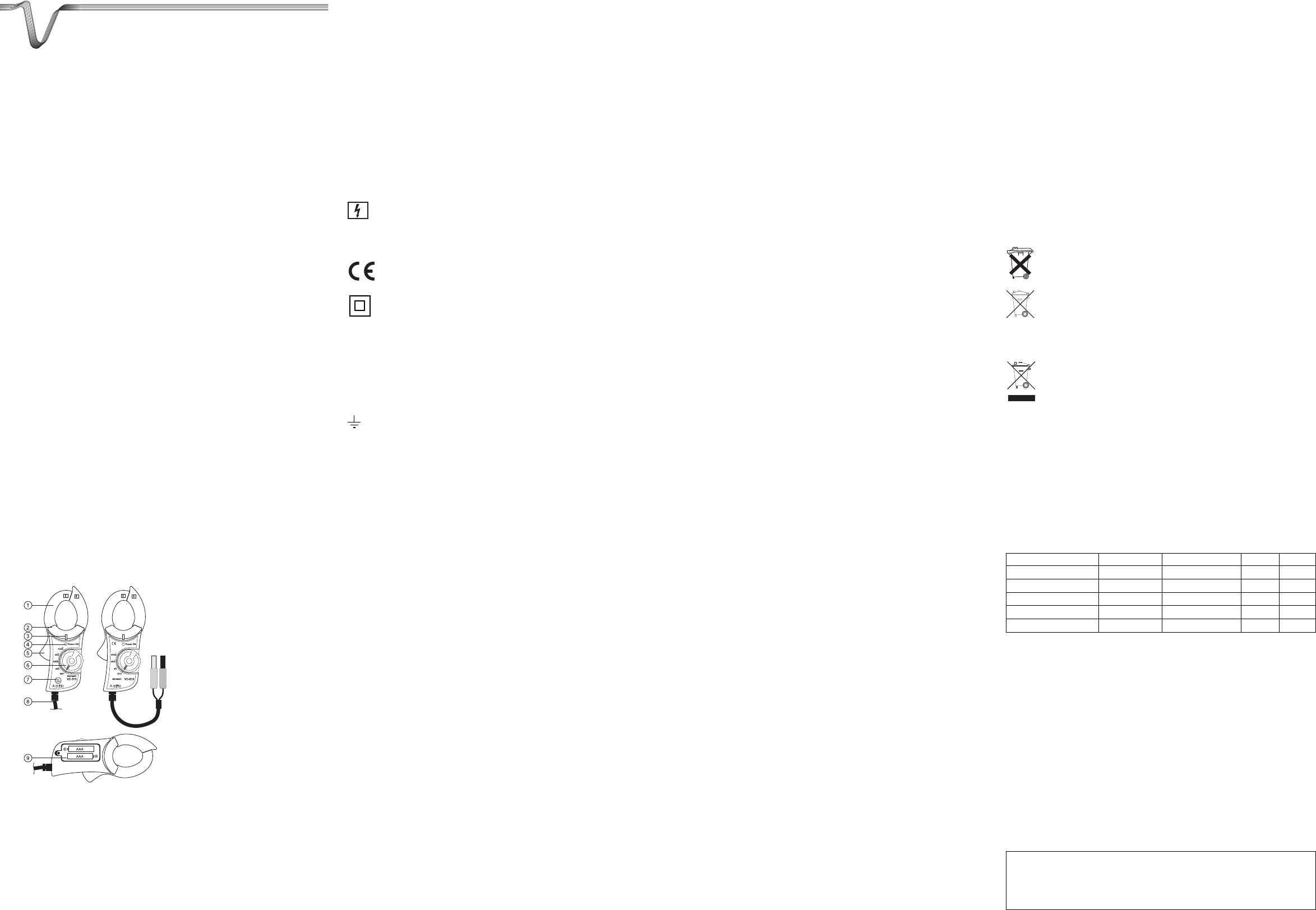
Controls
1 Clamp meter sensor
2 Grip area marking
3 LED display for contactless voltage
measurement (NCV)
4 Power indicator „POWER ON“
5 Opening lever for clamp meter sensor
6 Rotary switch
7 DC nullification (only VC-511)
8 Connecting line for voltmeter
9 Battery compartment (on reverse side)
Safety instructions
ƽ
Please read all of the operating instructions before using the product for the
first time; they contain important information regarding the correct operation.
The warranty will be void in the event of damage caused by failure to observe
these safety instructions! We do not assume any liability for any consequen-
tial damage!
We do not assume any liability for material and personal damage caused by
improper use or non-compliance with the safety instructions! The warranty will
be void in such cases.
This device left the manufacture’s factory in a safe and perfect condition.
We kindly request the user to observe the safety instructions and warnings contained in the enclosed
operating instructions so this condition is maintained and to ensure safe operation.
Please pay attention to the following symbols:
ƽ
A triangle containing an exclamation mark indicates important information in these
operating instructions which is to be observed without fail.
A lightning bolt symbol in a square warns of and allows access to non-insulated con-
ductors (dangerous active conductors).
☞
The “hand” symbol informs you that there are special tips and hints concerning the
operation.
This product has been CE-tested and meets the necessary European guidelines.
Class 2 insulation (double or reinforced insulation)
CAT III Overvoltage category III for measuring in building installation (e.g. outlets or sub-dis-
tribution). This category also covers all smaller categories (e.g. CAT II for measuring
electronic devices).
CAT IV Overvoltage category IV for measuring the source of the low volage installation (e.g.
between the sub-distribution and the main transfer point of the utility company). This
category also contains all lower categories.
Ground potential
The unauthorized conversion and/or modification of the product is not allowed for reasons of
safety and approval (CE).
If you have doubts about how the equipment should be operated or how to connect it safely, con-
sult a trained technician.
Measuring instruments and accessories are not toys and have no place in the hands of children.
On industrial sites, the accident prevention regulations of the association of the industrial work-
ers’ societies for electrical equipment and utilities must be followed.
In schools, training centres, computer and self-help workshops, handling of measuring instru-
ments must be supervised by trained personnel in a responsible manner.
The voltage between the measuring device and the ground potential must not exceed 600
V DC/AC in overvoltage category III or 300 V DC/AC in overvoltage category IV.
Take particular care when dealing with voltages exceeding 25V alternating (AC) resp.
35V direct current (DC)! Even at such voltages you can receive a life-threatening electric shock
if you come into contact with live electric wires.
Check the measuring device and its measuring lines for any damage(s) before each measure-
ment. Never carry out any measurements if the protecting insulation is defective (torn, ripped
off, etc.)
To avoid an electric shock, make sure not to touch the connections/measuring points to be meas-
ured neither directly nor indirectly during measurement. During measuring, do not grip beyond
the tangible grip range markings.
Do not use the adapter just before, during or just after an electrical storm (electrical shock! / high-
energy overvoltages!). Please make sure that your hands, your shoes, your clothing, the floor,
switches and switching components are dry.
Avoid operation near:
- strong magnetic or electromagnetic fields
- transmitter aerials or HF generators,
These can affect the measurement.
If there is any reason to believe that safe operation has become impossible, turn the device off
and secure it against any unintentional operation. It can be assumed that safe operation is no
longer possible if:
- the device shows visible damage,
- the device no longer operates and
- after being stored under unfavourable conditions for a long period of time or
- it has been subjected to considerable stress in transit
Never switch the device on immediately after having taken it from a cold in to a warm environ-
ment. The condensation that forms might destroy your device. Allow the device to reach room
temperature before switching it on.
Be exceptionally careful when measuring on current conductors and non-insulated conductors -
there is a risk of an electric shock. Wear protective equipment (e.g. gloves) in accordance with
the applicable safety guidelines in order to prevent injury from electric shocks and arcs, etc.
Do not leave the packaging material lying around carelessly since such materials can become
dangerous toys in the hands of children.
Do not work alone if possible, to allow help to be available if required.
You should also heed the safety instructions in each chapter of these instructions.
Information and symbols
AC~ Alternating current
DC= Direct current
A Ampere (unit of electric current)
DC ZERO Nullification for DC current range
Power ON Power indicator
Start-up
Inserting/replacing the batteries
Prior to working with the clamp meter adapter, you have to insert the enclosed batteries. If the
power indicator „Power ON“ (4) is not illuminated while switched on, you need to replace the bat-
teries.
To insert/replace the batteries, proceed as follows:
Unplug the adapter from all circuits and switch off the device (OFF).
Unscrew the battery compartment lid on the back (9) and remove the lid.
Place two identical new batteries with the correct polarity into the battery compartment. Observe
of the polarity markings (+ and -) in the battery compartment.
Close the battery compartment again carefully.
☞
You can order suitable alkaline batteries stating the following order no.: Order no.: 65
23 03 (please order 2).
Connection to a voltameter
Connect the output jack (8) with the voltage measuring connectors of the measuring device. In
case of direct current the red connector relates to the positive pole, the black connector to the
negative pole (COM).
Alternating current measuring A~
Connect the connector of the connecting line to the voltage input of the measuring device and
switch it on.
Select the testing range for 400 mV/AC on the voltameter.
On the clamp meter adapter, select the testing range that suits best your use.
Open the clamp meter sensor by pushing the opening lever (5).
Always clamp just one conductor with the clamp meter, otherwise the currents cancel each oth-
er out and incorrect measure values are indicated.
The current can be read on the measuring device when the consumer is active.
The following alternating voltages are emited in proportion to the measured current.
4 A range 100 mV/A (only VC510)
40 A range 10 mV/A
400 A range 1 mV/A
☞
If necessary, use the optionally available current measuring adapter of the CLA
series for one and three phase connecting cables. These facilitate the measuring on
hard-wired power cables.
Direct current measuring A= (only VC511)
Connect the connector of the connecting line to the voltage input of the measuring device (red
connector = positive pole, black connector = negative pole) and switch it on.
Select the testing range for 400 mV/DC on the voltameter.
On the clamp meter adapter, select the testing range that suits best your use.
Keep the clamp meter closed and turn the DC nullification (7) until the voltameter indicates 0 mV.
Perform this nullification prior to each measuring operation to prevent wrong measuring
results.
Open the clamp meter sensor by pushing the opening lever (5).
Always clamp just one conductor with the clamp meter, otherwise the currents cancel each oth-
er out and incorrect measure values are indicated. Observe the current flow direction of the pow-
er cable (from power source to consumer). This flow direction is indicated on the clamp meter
sensor by an arrow and runs from the front to the back.
The currect can be read off on the measuring device when the consumer is active.
If negative current is indicated, the flow runs in the opposed direction (e.g. while charging) or the
flow direction was interchanged on the clamp meter.
The following direct voltages are emited in proportion to the measured current.
40 A range 10 mV/A
400 A range 1 mV/A
☞
If nullification is not possible, open and close the clamp several times in a row.
Contactless AC voltage testing 90 - 600 V/AC
The clamp meter adapter also enables the contactless detection of alternating current-carrying
conductors. If alternating voltage is detected, the NCV display (3) lights up. The voltage tester is
active in any measuring range.
To test voltage, proceed as follows:
Switch the clamp meter adapter on with the rotary switch (6). The measuring range is not rele-
vant herewith.
Test this function on a known power source (e.g. socket).
Lead the protruding probe of the clamp meter sensor (1) close along the current conductor. When
conductors are twisted a longer conductor section needs to be tested.
☞
This function is very sensitive and may also respond to static influences upon touch-
ing. This is normal and does not influence the measuring result.
ƽ
This function is intended for fast fault diagnostics. Before commencing work on these
conductors a contact measurement needs to be carried out to verify that they are free
of voltage.
Disposal of used batteries!
The user is legally obliged (battery regulation) to return used batteries and storage batteries.
Do not dispose of used batteries via the household rubbish!
Batteries/rechagable batteries containing harmful substances are marked with the
following symbols, which point out that disposal in the domestic waste is prohibited.
The symbols for the relevant heavy metals are: Cd = cadmium, Hg = mercury, Pb =
lead. You can dispose of your used batteries/rechargeable batteries free of charge
at your community’s collection point or any place where batteries/rechargeable bat-
teries are sold!
You therefore fulfil the legal requirements and make your contribution to the
protection of the environment!
Disposal
Electronic products are raw material and do not belong in the household waste.
When the device has become unusable, dispose of it in accordance with the current
statutory regulations at the communal collection points. Disposal in the domestic
waste is not permitted!
Troubleshooting
ƽ
Only an authorised expert may perform repairs.
If you have queries about handling the measuring device, our technical support is
available under the following telephone number:
Voltcraft®, 92242 Hirschau, Lindenweg 15, phone 0180 / 586,582 7
Technical Data
Power Supply ..............................................2 AAA batteries
Opening range clamp meter sensor ............ 30 mm
Over-voltage category..................................CAT IV 300 V, CAT III 600 V
Working conditions ...................................... 0 - +50°C, max. 70%rF
Tolerance indication ....................................at 25°C +/- 5°C and <70%rF
Range Definition Tolerance VC510 VC511
0 - 4 A/AC (50/60 Hz) 100 mV/A +/-(2.5% + 0.3 A) X
0 - 40 A/AC (50/60 Hz) 10 mV/A +/-(2.5% + 0.1 A) X X
0 - 400 A/AC (50/60 Hz) 1 mV/A +/-(2.8% + 0.5 A) X X
0 - 40 A/DC 10 mV/A +/-(2.5% + 0.1 A) X
0 - 400 A/DC 1 mV/A +/-(2.8% + 0.5 A) X