Recommended P
Cable (A 24 22 20 18 16
12 V DC maximum cable length m (ft.) 5 (16.4) 9 (29.5) 14 (45.9) 23 (75.5) 32 (105.0)
24 V AC maximum cable length m (ft.) 11 (36.1) 18 (59.1) 29 (95.1) 46 (150.9) 64 (210.0)
Use UL cable (UL-1015 or equivalent) for 12 V DC or 24 V AC wiring.
A
Please use the dedicated AC adapter (sold separately).
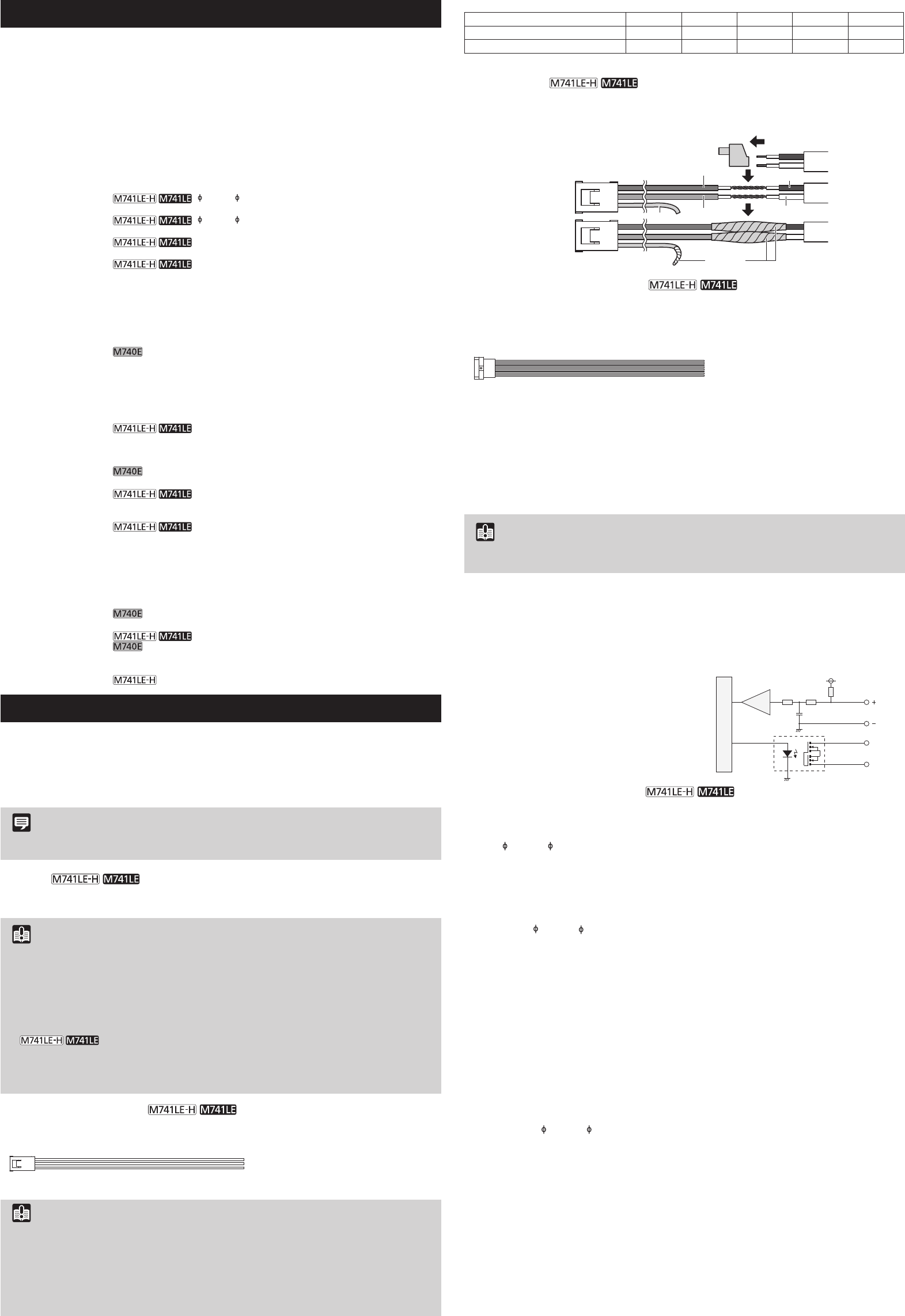
Remove the power connector attached to the AC adapter
cable included in the package, to the power connector
AC Adapter
Power Interface
Cable
Black
Brown
Blue
Green
White
Insulate
External Device I/O T
External device I/O ter
be used to check external device input status and control output to an external device (please
refer to the “Operation Guide”).
Use the included I/O interface cable to connect to exter
1: BROWN External device input 1 IN1 (+)
2: BLACK External device input 1 IN1 (-)
3: RED External device input 2 IN2 (+)
4: BLACK External device input 2 IN2 (-)
5: ORANGE External device output 1 OUT1
6: YELLOW External device output 1 OUT1
7: GREEN External device output 2 OUT2
8: BLUE External device output 2 OUT2
1
8
Exter
External device input ter
terminals connected to the camera interior GND. Connecting cables to the positive and
negative terminals and opening or closing the circuit notifies the Viewer
Impor
When connecting sensors and switches, connect terminals that are electrically isolated from the
respective power and GND.
Exter
External device output ter
have no polarity
the terminals. Using optical couplers, the output ter
internal circuit.
Internal Connection Diagram
Internal controller
External device
Input terminal
IN1, IN2
Output terminal
OUT1, OUT2
+3.3 V
0.1 µF
10 kΩ 10 kΩ
1 kΩ
External device
The load connected to the output terminals
should be within the following rating range.
Rating between output terminals:
Continuous load current at or below 100 mA
On resistance: Max. 30 Ω
Audio Input/Output T
Each audio input/output terminal has one input system and one output system.
Connecting the camera to an audio input/output device such as a microphone or a speaker
with an amplifier allows you to send/receive audio thr
Use the
3.5 mm ( 0.14 in.) monaural mini-jack connector to connect an audio input/output
device.
A
Although the camera has a single audio input system, it supports two types of microphone
input: LINE IN and MIC IN. Before using the audio input, please confirm the [Audio Input] in the
Setting Page (please refer to the “Operation Guide”). LINE IN is selected by default.
Input terminal:
3.5 mm ( 0.14 in.) mini jack (monaural)
•
Input impedance: 1.5 kΩ ±5%
* Supported microphones: Output impedance: 400 – 600 Ω
•
Input impedance (microphone bias rΩ ±5%
Microphone power supply: plug-in power (voltage: 2.3 V)
* Supported microphones: Condenser microphones with plug-in power support
•
Input level: Max. 1 Vp-p
* Use a microphone with an amplifier
A
Connect the camera to a speaker with an amplifier
Viewer
Output terminal:
3.5 mm ( 0.14 in.) mini jack (monaural)
Output level: Max. 1 Vp-p
* Use a speaker with an amplifier
© CANON INC. 2017 Printed in Japan
Specifications
Please refer to the Appendix – Specifications for specifications not listed below
Lens 2.4x optical zoom (4x digital zoom) lens (electric drive)
Viewing Angle For 16:9 aspect ratios
Horizontal: 113.4° (W) – 46.5° (T)
V
For 4:3 aspect ratios
Horizontal: 113.4° (W) – 46.5° (T)
V
Pan Angle Range 344° (±172°)
Tilt Angle Range 93° (-3° – +90°)
and 90° when at a horizontal position.
Rotation Angle Range 344° (±172°)
Network T LAN x 1 (RJ45, 100Base-TX (auto/full-duplex/half-duplex))
* Use a category 5 or better LAN cable, 100 m (328 ft.) or less in length.
Audio Input T
3.5 mm ( 0.14 in.) mini-jack connector (monaural)
(Common LINE IN & MIC IN)
Audio Output T
3.5 mm ( 0.14 in.) mini-jack connector (monaural)
(LINE OUT)
External Device I/O T
Input x 2, Output x 2
Memory Card SD Memory Card, SDHC Memory Card, SDXC Memory Card Compatible.
Operating Environment
T
Operating T
AC, PoE+: -50°C – +55°C (-58°F – +131°F)
DC, PoE: -10°C – +55°C (+14°F – +131°F)
Start-up T
AC, PoE+: -30°C – +55°C (-22°F – +131°F)
DC, PoE: -10°C – +55°C (+14°F – +131°F)
Humidity: 5% – 85% (without condensation)
T
Operating T
PoE: -10°C – +55°C (+14°F – +131°F)
Humidity: 5% – 85% (without condensation)
Storage Environment T
Humidity: 5% – 90% (without condensation)
Installation Method Ceiling mount/Surface mount
Power Supply
PoE:
(IEEE802.3at T
AC Adapter: P
External power source: 24 V AC/12 V DC
PoE:
(IEEE802.3at T
IR Illumination Range
(T)
30 m (98.4 ft.) (When using 24 V AC, PoE+)
20 m (65.6 ft.) (When using 12 V DC, PoE)
Power Consumption
PoE+: Max. approx. 21.2 W*
1
PoE: Max. approx. 10.1 W*
2
AC Adapter P
Max. approx. 12.8 W (240 V AC)
DC: Max. approx. 11.1 W
AC: Max. approx. 22.2 W
*
1
Class 4 power sourcing equipment (r
*
2
Class 0 power sourcing equipment (r
PoE: Max. approx. 7.4 W*
* Class 0 power sourcing equipment (r
Weight
Approx. 2120 g (4.68 lb.)
Approx. 2040 g (4.50 lb.)
Dust-resistant/
W IP66
Hydrophilic Coating
Available
Connecting the Camera
T
insulating tape, and then wrap all of the cables with waterproofing tape.
Power Connection
Power can be supplied to the camera in the three ways described below
read the user manual for the dedicated power supply befor
Note
•
•
P /P
Power can be supplied to the camera by using a LAN cable connected to a PoE+/PoE HUB
that conforms to the IEEE802.3at T
Impor
•
Midspan (a LAN cable power supply device) is a device that, like a PoE+/PoE HUB, supplies power
to the camera via a LAN cable.
•
with perfor
•
with perfor
for your PoE+/PoE HUB.
•
When the camera is connected to both a PoE+/PoE HUB and an external power
supply (12 V DC or 24 V AC), power will be supplied in the following order of pr
External power supply (24 V AC) > PoE+/PoE HUB > Exter
However
unstable network connections. If a problem arises, disable one of the power supplies.
Exter
12 V DC or 24 V AC input can be used. Use the included power interface cable to connect to
the camera power connection terminal.
1
3
1: BROWN Power 24 V AC / 12 V DC non-polar
2: BLUE Power 24 V AC / 12 V DC non-polar
3: GREEN FG (frame ground)
12 V DC can be connected in a non-polar configuration.
Impor
•
The power supply should be within the following voltage range.
•
Current supply capacity of at least 1.0 A per camera
•
Current supply capacity of at least 1.5 A per camera
•
Ω/20 W
in series to the power line.
•
CANON INC
30-2, Shimomaruko 3-chome, Ohta-ku, T
CANON EUROP
Bovenkerkerweg 59, 1185 XB Amstelveen, The Netherlands