700477
1
Zoom out
Zoom in
Vorherige Seite
1/2
Nächste Seite
Remote Turn-On
[FR–]
[FR+]
[SUB–]
[SUB+]
[FL–]
[FL+]
[SUB IN]
Source
[REM]
Battery
Fuse
(not included)
[+12V]
[GND]
[FRONT IN]
Thank you for purchasing a JL Audio amplifier for
your sound system.
Your amplifier has been designed and manufactured to exacting
standards in order to ensure years of musical enjoyment. For maximum
performance, we highly recommend that you have
your new amplifier installed by an authorized JL Audio dealer. Your
authorized dealer has the training, expertise and installation equipment
to ensure optimum performance from this product. Should you
decide to install the amplifier yourself, please take the time
to read this manual thoroughly to familiarize yourself
with its installation requirements and setup procedures.
If you have any questions regarding the instructions in this
manual or any aspect of your amplifier’s operation, please contact your
authorized JL Audio dealer for assistance. If you need further assistance,
please call the JL Audio Technical Support Department
at technical@jlaudio.com or call (954) 443–1100 during business hours.
OWNER’S MANUAL
600W 3-Channel Class D System Amplier
What’s Included
(1) Amplifier
(4) Stainless steel mounting screws
(1) User manual
Product Description
This is a three-channel, system amplifier utilizing Class D technology for all
channels.
Installation Applications
This amplifier is designed for operation with 12 volt, negative-ground electrical
systems. Using this product in systems with positive ground and/or voltages
other than 12V may result in damage to the product and will void the warranty.
This product is not certified or approved for use in aircraft.
Safety Considerations
Whenever possible, mount the amplifier in a dry, well-ventilated location
that does not interfere with other factory installed electronic devices. If a dry
environment is not available, a location that is not exposed to heavy splashing
may be used.
While this amplifier is designed to be water-resistant, it should never be
submerged under water or subjected to high-pressure water spray.
Do not install where it will be directly exposed to the elements.
Do not mount the amplifier in the engine compartment or in any areas of
extreme heat.
Securely mount the amplifier so that it does not come loose in the
event of a collision/sudden jolt or as a result of repeated vibrations during
normal operation.
Check before drilling to make sure that you will not be drilling into an exterior
panel/hull, fuel tank, gas/brake line, wiring harness, or other vital system.
Do not run system wiring outside or underneath the vehicle/vessel. This is an
extremely dangerous practice, which can result in severe damage/injury.
Protect all system wires from sharp edges (metal, fiberglass, etc.) by
carefully routing them, tying them down and using grommets and loom
where appropriate.
Secure all wiring as needed, using cable ties or wire clamps to protect them
from moving parts and sharp edges.
IPX7 Water Resistance Rating
This product has been tested to withstand immersion in water, up to 1 meter
(3.28 ft.) deep, for up to 30 minutes (with control panel cover properly installed).
Note - while designed to be water resistant, this product should never be
submerged under water for prolonged periods or subjected to activity that
creates pressure on it that exceeds its depth rating.
Installation Procedure/Connections
1. Disconnect the NEGATIVE battery post connection and secure the
disconnected cable to prevent accidental reconnection during installation.
This is an essential safety precaution during installation!
2. Connect the RED power lead to the positive (+12V) battery post. 4 AWG is
the minimum power wire size for this amplifier.
3. An appropriate fuse (sold separately), such as the JL Audio Water-Resistant
Master MAXI™ Fuse Block (XD-MFBW-MAXI), at the main power wire(s) to
the amplifier(s) is vital for vehicle/vessel safety. This fuse must be installed
within 18 inches (45 cm) of the positive battery post connection. If this is
the only device connected to this main wire, use a 60A fuse. Do not install
the fuse until the power wire has been securely connected to the amplifier.
4. Connect the BLACK negative ground lead to a clean, solid metal grounding
point near the amplifier. This can be to metal chassis ground, if available.
If no metal chassis ground is available, it may be necessary to make this
connection to the NEGATIVE battery post. 4 AWG is the minimum ground
wire size for this amplifier. All ground connections (source unit and
amplifiers) should be made at the same location.
5. Connect the BLUE remote turn-on lead to the source unit’s positive (+12V)
remote turn-on output. If your source unit does not have a dedicated
remote turn-on output, the amplifiers turn-on lead can be connected to
+12V via a switch that derives power from an ignition-switched circuit.
6. Signal Input (Low-Level): Connect the amplifiers RCA input jacks to the
source unit’s preamp level output jacks.
7. Signal Input (High-Level): If your source unit does not offer preamp level
signal outputs, you can splice the speaker output wires of the source unit
onto a pair of RCA plugs for each input pair or use the JL Audio ECS Speaker
Wire to RCA adaptor (XD-CLRAIC2-SW). Make sure to observe correct
polarity in making “High-Level Input connections. Failure to do so will result
in a loss of signal (poor performance).
8. Connect the speaker output leads to the corresponding speaker wires.
9. Make necessary adjustments to the filter controls and input sensitivity.
10. The amplifier’s subwoofer output level can be controlled from the front
of the vehicle/vessel with an optional remote level controller (sold
separately). Use the RBC-1 for standard (dry) installations or the M-RBC-1
for applications exposed to moisture. Connect the remotes plug to the
amplifiers harness-mounted RJ11 input jack. (Refer to Appendix B)
WARNING! Failure to make safe, tight, high-integrity power connections
can result in fire and extensive damage!
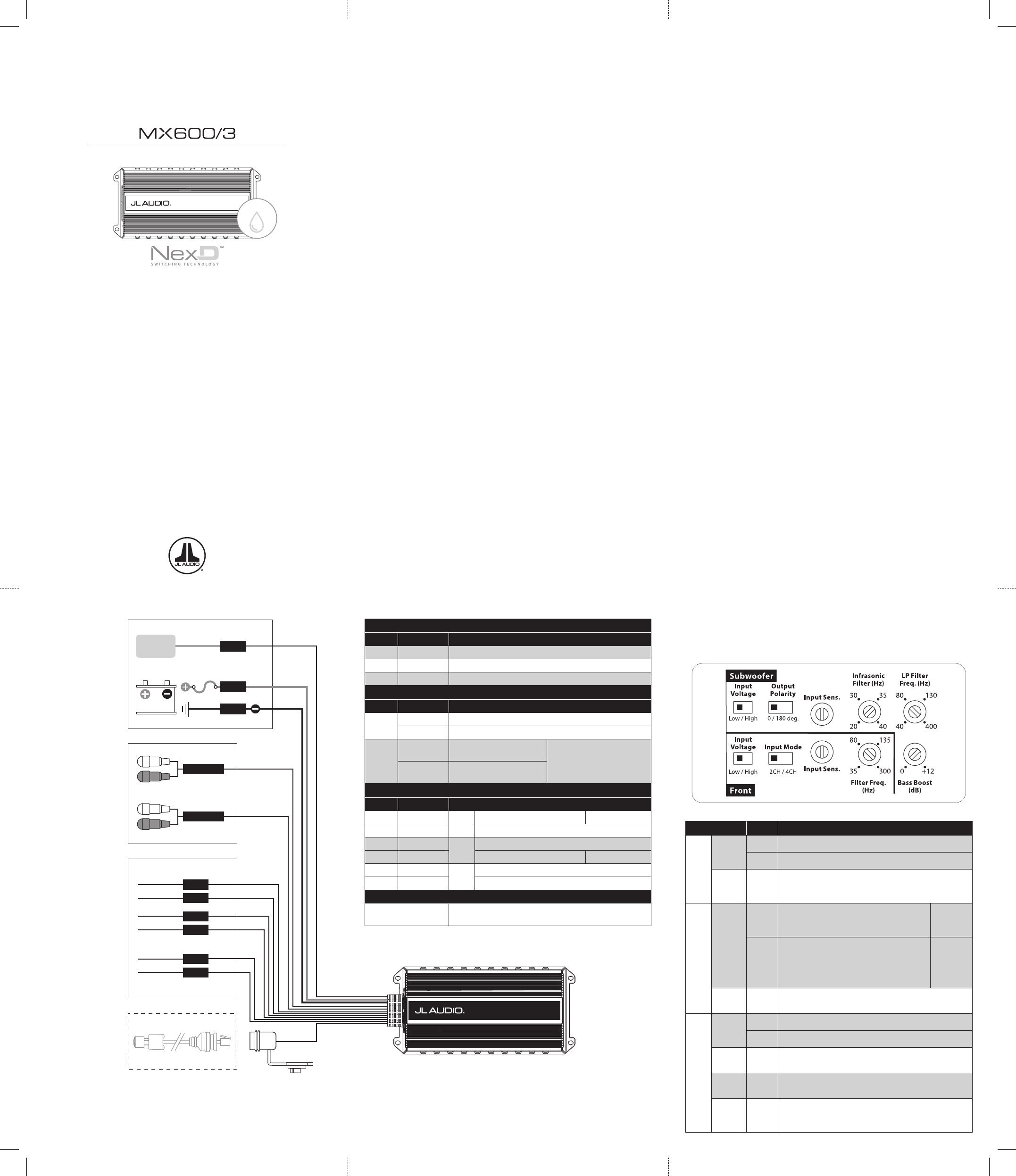
Control Setting Mode / Function
Front / Subwoofer
Input
Voltage
Low RCA/Preamp Level Range (250 mV - 4 V)
High RCA/Preamp or Speaker Level Range (580 mV - 14 V)
Input
Sens.
Variable
Adjusts the input stage of each pair of amplifier channels to
match the source unit’s output voltage for maximum clean
output (refer to Appendix A)
Front
Input
Mode
2CH
Applies two channels of input to all three
amplifier channels. Main input signals will be
combined to mono for the subwoofer channel.
Use Front
Inputs Only
4CH
Sends four discrete channels to all four inputs.
L & R Sub Inputs will be combined to mono.
If only one channel of subwoofer signal is
available, we recommend using a Y-adaptor to
feed both Sub Inputs.
Use Front
and Sub
Inputs
Filter
Freq. (Hz)
Variable
Adjusts the high-pass filter cutoff frequency, variable from
35-300 Hz, 12 dB/Octave
Subwoofer
Output
Polarity
0 Normal speaker polarity
180 deg. Polarity reversed 180 degrees
Infrasonic
Filter (Hz)
Variable
Adjusts the high-pass filter cutoff frequency, variable from
20-40 Hz, 12 dB/Octave
LP Filter
Freq. (Hz)
Variable
Adjusts the low-pass filter cutoff frequency, variable from
40-400 Hz, 24 dB/Octave
Bass
Boost (dB)
Variable
Boost-Only Bass Equalizer: Boost range from 0dB (full-
counterclockwise) to + 12dB (full-clockwise), centered
at 43 Hz.
Control Panel Settings and Adjustments
The amplifier’s settings and controls are located on the bottom panel beneath a
gasketed, protective cover. Remove the four Phillips head screws from the center
panel to access the controls and make adjustments. Replace cover when finished
and mount the amplifier.
Power Connections
Label Wire Color Description
+12V Red Positive (+12V) Power Connection
GND Black Negative (GND) Ground Connection
REM Blue Positive (+12V) Remote Turn-On Input
Inputs
Label Plug Description
FRONT
IN
White RCA Ch. 1 / Front Left Channel Signal Input
Red RCA Ch. 2 / Front Right Channel Signal Input
SUB
IN
White RCA
Ch. 3 / Left Subwoofer
Channel Signal Input
Note: L & R Sub Inputs will be
combined to mono. If only one
channel of subwoofer signal is
available, we recommend using a
Y-adaptor to feed both Sub Inputs.
Red RCA
Ch. 4 / Right Subwoofer
Channel Signal Input
Outputs
Label Wire Color Description
FL+ White
Ch. 1
(+) Positive Front Left Speaker Front Bridged (+)
FL– White/Black (–) Negative Front Left Speaker
FR+ Gray
Ch. 2
(+) Positive Front Right Speaker
FR– Gray/Black (–) Negative Front Right Speaker Front Bridged (–)
SUB+ Lt. Blue
Ch. 3
(+) Positive Subwoofer Output
SUB– Lt. Blue/Black (–) Negative Subwoofer Output
Optional
Remote Bass
Control Jack
RJ11 Input Jack for M-RBC-1 or RBC-1 (each sold separately)
Connections
IPX7
WATER
RESISTANT
Power
Connections
Wiring Diagram
Outputs:
To Speakers
Inputs:
High-Level
< or >
Low-Level
(selectable via
Input Voltage
switch for each
channel pair)
Optional:
M-RBC-1
Remote
Bass Control
(sold separately)
1

Brauchen Sie Hilfe? Stellen Sie Ihre Frage.

Forenregeln

Missbrauch melden von Frage und/oder Antwort

Libble nimmt den Missbrauch seiner Dienste sehr ernst. Wir setzen uns dafür ein, derartige Missbrauchsfälle gemäß den Gesetzen Ihres Heimatlandes zu behandeln. Wenn Sie eine Meldung übermitteln, überprüfen wir Ihre Informationen und ergreifen entsprechende Maßnahmen. Wir melden uns nur dann wieder bei Ihnen, wenn wir weitere Einzelheiten wissen müssen oder weitere Informationen für Sie haben.

Art des Missbrauchs:

Zum Beispiel antisemitische Inhalte, rassistische Inhalte oder Material, das zu einer Gewalttat führen könnte.

Beispielsweise eine Kreditkartennummer, persönliche Identifikationsnummer oder unveröffentlichte Privatadresse. Beachten Sie, dass E-Mail-Adressen und der vollständige Name nicht als private Informationen angesehen werden.

Forenregeln

Um zu sinnvolle Fragen zu kommen halten Sie sich bitte an folgende Spielregeln:

Neu registrieren

Registrieren auf E - Mails für JL Audio MX600 wenn:


Sie erhalten eine E-Mail, um sich für eine oder beide Optionen anzumelden.


Das Handbuch wird per E-Mail gesendet. Überprüfen Sie ihre E-Mail.

Wenn Sie innerhalb von 15 Minuten keine E-Mail mit dem Handbuch erhalten haben, kann es sein, dass Sie eine falsche E-Mail-Adresse eingegeben haben oder dass Ihr ISP eine maximale Größe eingestellt hat, um E-Mails zu erhalten, die kleiner als die Größe des Handbuchs sind.

Ihre Frage wurde zu diesem Forum hinzugefügt

Möchten Sie eine E-Mail erhalten, wenn neue Antworten und Fragen veröffentlicht werden? Geben Sie bitte Ihre Email-Adresse ein.


Info