Nota:
• Esta unidad es para vehículos con una batería de
12 voltios y masa negativa. Antes de montarlo en
un autobús, camión o vehículo de recreación,
compruebe el voltaje de la batería.
• Para evitar cortocircuitos en el sistema eléctrico,
cerciórese de desconectar el cable de batería (–)
antes de comenzar la instalación.
• Para los detalles sobre la conexión a otras
unidades, refiérase al manual del propietario y
luego haga las conexiones correctamente.
• Asegure el cableado con grapas de cable o cinta
aisladora. Para proteger el cableado, envuelva con
cinta aisladora alrededor del cableado en las partes
en donde se apoya contra las partes metálicas.
• Pase y asegure todo el cableado de modo que no
toque ninguna de la partes móviles, tales como
engranaje de cambio, freno de mano y carriles del
asiento. No pase el cableado por lugares que se
calientan, tales como cerca una salida del calefactor.
Si la aislación del cableado se derrite o se rompe,
existe el peligro de que el cableado se ponga en
cortocircuito con la carrocería del vehículo.
• No pase el conductor amarillo a través de un orifi-
cio en el compartimiento del motor para conectar
a la batería. Esto dañará el material aislante del
conductor y causará un cortocircuito peligroso.
• No ponga en cortocircuito ninguno de los conduc-
tores. Si lo hace, el circuito de protección fallará
en el momento que deba funcionar.
• No alimente otro equipo cortando la aislación del
conductor de suministro de alimentación de la
unidad y enrrollando en el conductor. La capaci-
dad actual del conductor será excedida, ocasion-
ando sobrecalentamiento.
• Cuando reemplace el fusible, cerciórese de usar
solamente el fusible indicado en el portafusible.
• Para evitar una conexión incorrecta, el lado de
entrada del conector IP-BUS es azul, y el lado de
salida es negro. Conecte los conectores de los
mismos colores correctamente.
• Para minimizar el ruido ubique el cable de la ante-
na de TV, el cable de la antena de radio y cable
RCA tan alejados como sea posible uno de otro.
Conexión del cable de
alimentación (Fig. 2)
1. Este producto
2. Portafusible
3. Amarillo
Al terminal con suministro constante de elec-
tricidad, independientemente de la posición
del interruptor de encendido.
4. Negro (masa)
A la carrocería del veículo (parte metálica).
Desconexión del conector AV-BUS
(Fig. 3)
Cuando desconecte un conector AV-
BUS, agárrelo firmemente en ambos
los lados y tire. Esto soltará el conec-
tor, permitiendo su desconexión.
• Los cables para esta unidad y aquéllas para
las unidades pueden ser de colores diferentes
aun si tienen la misma función. Cuando se
conecta esta unidad a otra, refiérase a los
manuales de instalación de ambas unidades y
conecte los cables que tienen la misma fun-
ción.
Conexión de las unidades <ESPAÑOL>
Nota:
• Antes de finalizar la instalación de la unidad,
conecte el cableado temporariamente, asegurán-
dose de que todo se encuentra conectado apropi-
adamente, y la unidad y el sistema funcionan
apropiadamente.
• Utilice solamente las partes incluídas con la
unidad para asegurar una instalación adecuada. El
uso de partes no autorizadas puede ocasionar fal-
las de funcionamiento.
• Si la instalación requiere del taladrado de orificios
u otras modificaciones del vehículo, consulte con
su agente o concesionario más cercano a su domi-
cilio.
• Instale la unidad en donde no interfiera con el
conductor y no pueda lesionar al pasajero en caso
de una parada repentina, tal como una frenada de
emergencia.
• Cuando monte esta unidad, cerciórese que ninguno
de los cables queda aprisionado entre esta unidad
y accesorios o partes metálicas circundantes.
• No monte esta unidad cerca de la salida del cale-
factor, en donde podría ser afectado por el calor o
cerca de las puertas, en donde la lluvia podría
salpicar sobre la misma. (Para evitar el riego de
fallos de funcionamiento producidos por las altas
temperaturas, evite la instalación en los lugares
arriba.)
• Antes de taladrar cualquier orificio de montaje
siempre compruebe lo que hay detrás en donde
desea taladrar los orificios. No taladre en la línea
de combustible, cableado eléctrico u otras partes
importantes.
• Si esta unidad es instalada en el compartimiento
de pasajeros, fíjela seguramente de modo que no
se desprenda mientras el automóvil se encuentra
en movimiento, y pueda ocasionar lesiones o acci-
dentes.
• Si esta unidad se instale bajo un asiento delantero,
cerciórese de que no obstruye el movimiento del
asiento. Pase todos los cables y conductores
cuidadosamente a través de los mecanismo
deslizantes, de modo que no queden aprisionados
o atrapados en el mecanismo y ocasionen un corto
circuito.
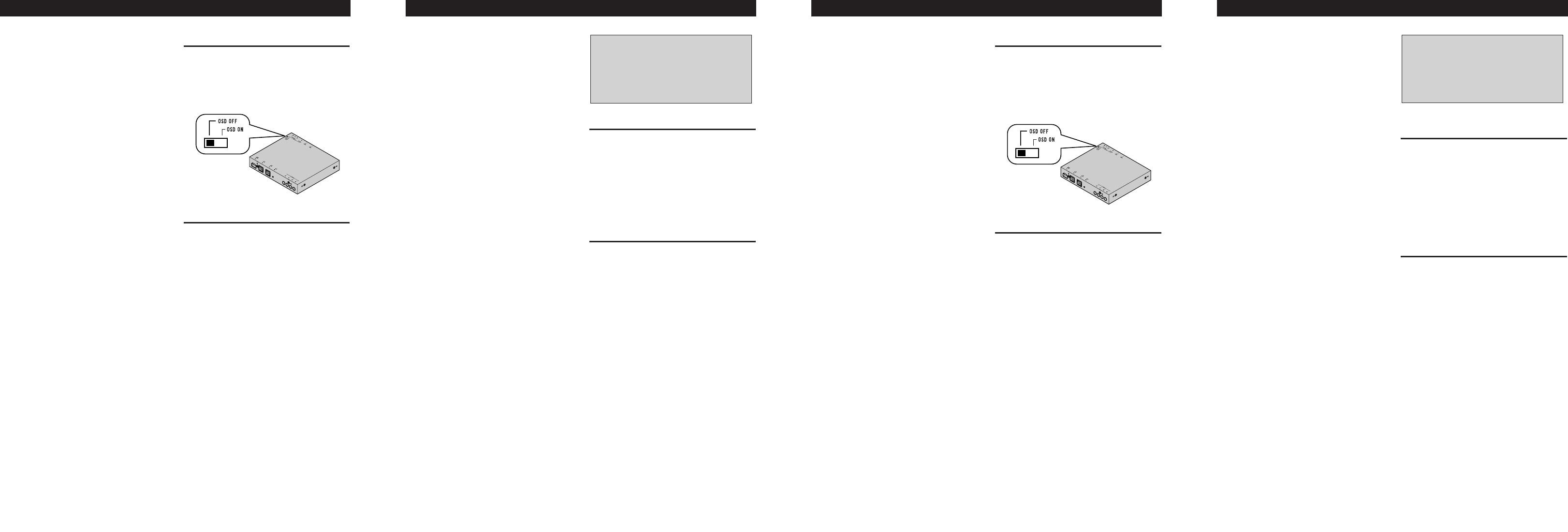
Ajuste del interruptor OSD
Antes de la instalación, utilice la punta
de un lápiz u otro elemento delgado y
puntiagudo, para ajustar el interruptor
OSD en el lado derecho de este pro-
ducto a la posición apropiada, para el
componente que se está usando.
Instalación de la unidad (Fig. 1)
Pegue la cinta Velcro (suministrada)
sobre la parte inferior de la unidad
oculta-alejada y pegue la cinta Velcro
blanda (suministrada) sobre el sitio de
instalación.
1. Este producto
2. Cinta Velcro (dura)
3. Cinta Velcro (blanda)
4. Alfombra del automóvil o chasis
Nota:
• La instalación directa sobre la alfombra es posible
si la cinta Velcro dura puede adherirse a la alfom-
bra. En este caso, no utilice cinta Velcro blanda.
• Limpie completamente la superficie antes de fijar
la cinta adherente o Velcro.
Instalación<ESPAÑOL>Connecting the Units <ENGLISH>
Note:
• Before finally installing the unit, connect the
wiring temporarily, making sure it is all connected
up properly, and the unit and the system work
properly.
• Use only the parts included with the unit to ensure
proper installation. The use of unauthorized parts
can cause malfunctions.
• Consult with your nearest dealer if installation
requires the drilling of holes or other modifica-
tions of the vehicle.
• Install the unit where it does not get in the driver’s
way and cannot injure the passenger if there is a
sudden stop, like an emergency stop.
• When mounting this unit, make sure none of the
leads are trapped between this unit and the sur-
rounding metalwork or fittings.
• Do not mount this unit near the heater outlet,
where it would be affected by heat, or near the
doors, where rainwater might splash onto it.
(Never install in locations such as the above
because of the danger of malfunction due to high
temperatures.)
• Before drilling any mounting holes always check
behind where you want to drill the holes. Do not
drill into the gas line, brake line, electrical wiring
or other important parts.
• If this unit is installed in the passenger compart-
ment, anchor it securely so it does not break free
while the car is moving, and cause injury or an
accident.
• If this unit is installed under a front seat, make
sure it does not obstruct seat movement. Route all
leads and cords carefully around the sliding mech-
anism so they do not get caught or pinched in the
mechanism and cause a short circuit.
OSD Switch Setting
Before installing, use a pen tip or other
thin, pointed instrument to set the OSD
Switch on the right side of this product
to the appropriate position for the com-
ponent you are using it with.
Installing the Unit (Fig. 1)
Adhere the hard Velcro tape (provided)
to the bottom of the hide-away unit and
adhere the soft Velcro tape (provided)
to the installation location.
1. This product
2. Velcro tape (hard)
3. Velcro tape (soft)
4. Car mat or chassis
Note:
• Direct installation on the carpet is possible if the
hard Velcro tape will adhere to the carpet. Do not
use the soft Velcro tape in this case.
• Thoroughly wipe off the surface before affixing
the velcro tape.
Installation <ENGLISH>
Note:
• This unit is for vehicles with a 12-volt battery and
negative grounding. Before installing it in a recre-
ational vehicle, truck, or bus, check the battery
voltage.
• To avoid shorts in the electrical system, be sure to
disconnect the (–) battery cable before beginning
installation.
• Refer to the owner’s manual for details on con-
necting the other units, then make connections
correctly.
• Secure the wiring with cable clamps or adhesive
tape. To protect the wiring, wrap adhesive tape
around them where they lie against metal parts.
• Route and secure all wiring so it cannot touch any
moving parts, such as the gear shift, handbrake
and seat rails. Do not route wiring in places that
get hot, such as near the heater outlet. If the insu-
lation of the wiring melts or gets torn, there is a
danger of the wiring short-circuiting to the vehicle
body.
• Don’t pass the yellow lead through a hole into the
engine compartment to connect to the battery.
This will damage the lead insulation and cause a
very dangerous short.
• Do not shorten any leads. If you do, the protection
circuit may fail to work when it should.
• Never feed power to other equipment by cutting
the insulation of the power supply lead of the unit
and tapping into the lead. The current capacity of
the lead will be exceeded, causing over heating.
• When replacing fuse, be sure to use only fuse of
the rating prescribed on the fuse holder.
• To prevent incorrect connection, the input side of
the IP-BUS connector is blue, and the output side
is black. Connect the connectors of the same col-
ors correctly.
• To minimize noise locate the TV antenna cable,
radio antenna cable and RCA cable as far away
from each other as possible.
Connecting the Power cord (Fig. 2)
1. This Product
2. Fuse holder
3. Yellow
To terminal always supplied with power
regardless of ignition switch position.
4. Black (ground)
To vehicle (metal) body.
Disconnecting an AV-BUS connector
(Fig. 3)
When disconnecting an AV-BUS con-
nector, grasp it firmly on both sides
and pull towards you. This will unlock
the connector, enabling disconnection.
• Cords for this product and those for other
products may be different colors even if they
have the same function. When connecting this
product to another product, refer to the sup-
plied Installation manuals of both products
and connect cords that have the same func-
tion.