Pant
blanco
El ciclocomputador está en
envío. Pulse un botón.
La pila
correct
Datos erró-
neos
El imán
lejos. Reajust
del sensor
La pila
Reemplace la pila.
Ninguna
velocidad
actual
El imán
lejos. Reajust
del sensor
La velocidad
no es cor-
recta.
El tamaño de
Rest
El sensor no
Reajust
sensor
Ninguna
cadencia
El imán
Reajust
sensor
Los contact
y la
computador no se encuentra en la
Reinstálelo
Ningún
ritmo
cardíac
La pila
a punto de
La correa de ritmo
contact
colóquela bien.
“Error” de
empareja-
miento
Asegúres
sensor están a una
pies (1 m) entre sí.
Compruebe la pila
Si el
información errónea,
agotando la
que el
cada 6
mejor es
la tienda.
•
Si se
blecerá automáticamente
a cero.
ajustar los
haber anotado
la pila.
1. Quite
2. Busque
3. Gírela
del reloj
4. R
T
5. Quite
6. Inserte
identificativa señalando
7. Vuelva a colocar
para pilas
de vuelta
Trek Bicycle
ciclocomputadores Incite
mano de
Esta garantía
putador de
Digital durante
la fecha
Esta garantía
normal, incluyendo
la batería.
• El
• La
pretendidos originalmente
bles con
• Daños
abuso o
Esta garantía
por cualquier
de sus
Esta garantía
la reparación
y es
garantía se
se aplica
no es
sable de
Algunos estados
daños consecuentes
exclusión anterior
a usted.
Las reclamaciones
hacerse a
Es necesaria
garantía concede
legales específicos
variar de
a los
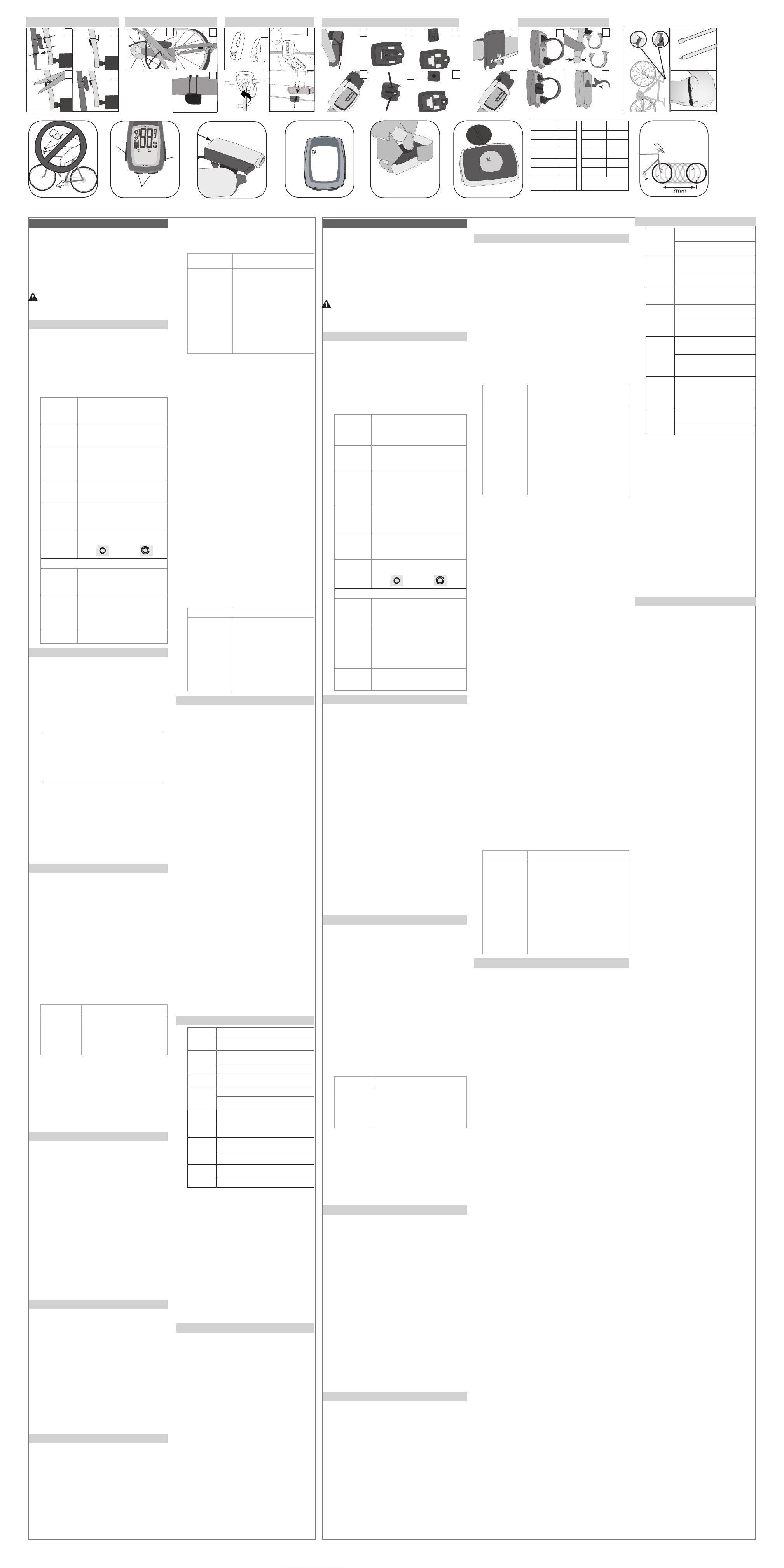
F4 F5 F6 F8
F3
700 x 20 2086 26 x 1.5 2010
700 x 23 2096 26 x 1.90 2045
700 x 25 2105 26 x 1.95 2050
700 x 28 2136 26 x 2055
700 x 32 2155 26 x 2.1 2068
700 x 35 2168 26 x 2.2 207
700 x 38 2180 Custom
0000 -
F7
F1
A
Mode
F2
C
Scroll
B
Set
25.4
26.0
31.8
1.0 -
3.0mm
2. Pulse los botones
cambia el
La velocidad
1. Pulse repetidamente el
SPEED.
2. Pulse repetidamente los
y MAX.
• AVG: velocidad media
• El
superior o
• MAX:
4
Mantenga pulsados se restablece
a 0.00.
1. Pulse repetidamente el
velocidad.
2. Mantenga 4aparece el
rueda.
3. Pulse repetidamente el 4 R
4. Pulse el botón
5. Pulse repetidamente los
alcanzar el
MENÚ DE
T
DE RUEDA
T
PERSONALIZADO
6. Pulse el
botón Ajuste
para selecci-
onar
7. Pulse el
botón Modo
4 aparece
la pantalla
de velocidad.
6. Determine
rueda (F8).
7. Pulse repetidamente el
desplazamiento hasta
4 cifras.
8. Mantenga
parpadea el
9. Pulse repetidamente el
desplazamiento hasta
10. Pulse el botón
confirmar la 4 parpadea
4 el siguiente dígito.
11. R
resto de
12. Pulse el botón 4 aparece la
pantalla SPD.
Para ajustar
seleccione la otra
1. Pulse repetidamente el
seleccionar CLOCK.
2. Pulse repetidamente los
seleccionar el
(00:00:00).
1. Pulse repetidamente el
seleccionar CLOCK.
2. Mantenga
4 parpadea 12 (horas
3. Pulse repetidamente los
seleccionar 12
4. Pulse el botón parpadea
la hora
5. Pulse repetidamente los
seleccionar la
6. Pulse el botón parpadean
los minutos.
7. Pulse repetidamente los
minutos.
8. Pulse el botón parpadea
la pantalla
1. Pulse repetidamente el
seleccionar ODOMETER.
2. Pulse repetidamente los
seleccionar TRP
1. Pulse repetidamente el
seleccionar ODOMETER.
2. Pulse repetidamente los
seleccionar TTL.
3. Mantenga 4parpadea el
dígito.
4. Pulse repetidamente los
seleccionar el
5. Pulse el botón parpadea
4 el siguiente dígito.
6. R
dígitos aparece
1. Pulse repetidamente el
seleccionar ODOMETER.
2. Pulse repetidamente los
seleccionar TRP
3. Mantenga 4parpadea MPH.
4. Pulse repetidamente los
seleccionar KMH
5. Pulse el botón parpadea
Fº.
6. Pulse repetidamente los
seleccionar F°
ciclocomputador:
LINK LINK TEAM
7. Pulse el
botón
Ajuste para
confirmar
la selección
4 aparece
La pantalla
TRP
7. Pulse el botón
la selección 4 aparece _CAd
(cadencia) con
ando.
8. Pulse repetidamente los
desplazamiento hasta
OFF u
9. Pulse el botón
la selección 4 aparece _Hr (ritmo
cardíaco) con
ando.
10. Pulse repetidamente los
de desplazamiento
OFF u
11. Pulse el botón
confirmar la 4 parpadea
4 La pantalla TRP
El ciclocomputador
(CAd) o
funciones o
“Unidades y
Si una
intentará EMP
P
en ON
1. Pulse repetidamente el
2. Pulse repetidamente los
seleccionar CUR,
1. Pulse repetidamente el
2. Mantenga 4 Se restablece
en 000.
P
cardíaco opcional
la función
medición” arriba).
1. Pulse repetidamente el
seleccionar Heart
2. Pulse repetidamente los
seleccionar CUR,
1. Pulse repetidamente el
RATE.
2. Mantenga 4 se restablece
en 000.
1. Pulse repetidamente el
Rate.
2. Pulse repetidamente los
seleccionar ZONE.
a. Aparece
b. Aparece
c. Aparece
1. Pulse repetidamente el
Rate.
2. Mantenga 4 aparece SET 4
parpadea el
3. Pulse repetidamente los
cambiar el
4. Pulse el botón 4 parpadea
4 el segundo dígito.
5. Pulse repetidamente los
cambiar el
6. Pulse el botón 4 parpadea
el tercer
7. Pulse el botón 4 parpadea
el límite
8. R4
aparece la
Presione firmemente
atrás (F3).
Lea detenidamente
referencia. Si
manual o
putador Incite
distribuidor Trek
Trek Bicycle
Attn: Customer
801 W
W
http://www
Cuando vaya
putador durante
(F1). Si
contra algún
control y
Hay cuatro
A: Modo
B: Ajuste
C: Desplazamiento
Existen tres
P
P
necesarias.
Mantener: mantener
CLOCK
CLK
TME
Hora del día, que
hora de conducción, que muestra los segundos.
F
horas
Lectur
de conducción)
ODOMETER
ODO
Distancia conducida, que se
kilómetros
TRP: trayect
TTL: total desde el último
Lectur
SPEED Siempre muestr
en millas
(KMH).
A
mostr
MAX: valor máximo desde el
Lectur
P Se muestra siempre
es más rápida
Se indica mediante una
(más rápido) o una fecha hacia
lento
TEMPERA Se muestra siempre
Indica la temperatur
Celsius en números enteros.
Lectur
Lectur
WHEEL
SELECTION
Se muestra siempre (F4).
Indica la configuración de piñón que
ciclocomputador
Rueda 1
Ru
CADENCE Rev
Aparec
Lectur
A
MAX: cadencia máxima
HEART RA
HR
Ritmo cardíaco en latidos por
CUR: actual
A
rest
MAX: ritmo cardíaco máximo desde el
rest
ZONE: las flechas indican
se encuentra dentro
de una
BACKLIGHT Propor
5 segundos.
Par
Modo.
Si el
pila), se
y se
(velocidad para
para Link
rápida, emparejamiento,
1. Instale
pequeño botón
putador
Aparecerá el
2. Pulse repetidamente el
cambiar el
Seleccione el tamaño
tamaño de
3. Pulse el botón 4parpadea
o MPH.
4. Pulse repetidamente el
cambiar el
5. Pulse el botón
parpadea Fº
6. Pulse repetidamente el
cambiar el
7. Pulse el botón
parpadea 12
8. Pulse repetidamente los
seleccionar el
9. Pulse el botón
parpadea la
10. Pulse repetidamente los
cambiar la
11. Pulse el botón
parpadean los
12. Pulse repetidamente los
cambiar los
13. Pulse el botón
parpadea SPEED
14. Sigua
Link y
de 2,4
los sensores
cardíaco. P
transmisiones, el
reconocer entre
exclusivo, de modo
interferencias.
Cada sensor
envía un
nado, el
de ese
sólo reconocerá
velocidad.
Existen dos
emparejamiento: el
Bajo demanda.
los datos
demanda no
inicial, siga
1. Coloque
metro) del
2. Haga
bicicleta para
o colóquese
3. Mantenga 4 P4
LINK LINK TEAM
4Aparece
la
pantalla
de
velocidad.
Suelte el
botón.
Aparece
4. Haga
señal (gire
cadencia).
5. Mantenga 4
P4 Aparece la
velocidad. Suelte
Si reemplaza
principal, o
Bajo demanda.
1. Coloque
metro) del
2. Haga
bicicleta para
o colóquese
3. Pulse ambos botones 4 P
4. Mantenga 4 P4 consulte
siguiente para
Cuando se
de ritmo
ninguna señal.
ninguna señal,
Tras cinco
desconecta de
modo de
búsqueda utiliza
idad, el
Desde el
recibir datos
sensor
1. Envíe
biela y/o
2. Pulse cualquier botón.
El ciclocomputador se
tardar algunos segundos. Si
de 20
cardíaco.
Si el ciclocomputador
“- -”.
la sección
1. Haga
pedalee la
2. Mantenga 4
parpadea “0” 4 ”0” 4 aparece el
valor
3. Suelte
Si aparece ---, compruebe
el sensor
emparejar el ciclocomputador o
Su ciclocomputador
total de
los datos
cardíaco se
cardíaco):
• ODOMETER
• SPEED
• CADENCE
• CLOCK
1. Pulse repetidamente el
2. Pulse repetidamente el
hora de
3. Mantenga
La configuración de
modo de
4. Suelte
El ciclocomputador
tamaños de
funciones, velocidad”.
como cambiar
1. Pulse repetidamente el
Please read
future reference.
information in
about your
cover
Trek Bicycle
Attn: Customer
801 W
W
http://www
While riding
computer for
not watch
which may
There are
A- Mode
B-
C-
There are
P
Cycle -
Hold-
CLOCK
CLK
TME
Time of day
Ride Time showing
12-hour (with AM/PM) or 24
Highest reading: 23:5
(Ride Time)
ODOMETER
ODO
Distance ridden, displays in miles or
TRP-
TTL
Highest reading: 99
SPEED Alwa
in miles per
hour (KMH)
A
played to tenths.
MAX
Highest readings: 80.5mph or 129.6kph
P Alwa
speed is
Displayed by arrow pointing up (fast
down (slow
TEMPERA Alway
Current temper
or Celsius in
Lowe
Highest reading: 140° F +/-2°, 60° C +/-1°
WHEEL
SELECTION
Alwa
Indicates which wheel setting is
computer
Wheel 1
Wh
CADENCE Rev
Displays in whole numbers
Highest reading: 2
A
MAX
HEART RA
HR
Rate of heart in beats
CUR- Current
A
MAX
ZONE
rat
or below the
BACKLIGHT Provide
T
When the
the battery)
your choice
must be
Heart R
Quick Set-up,
1. Install
silver button
cover) Wheel
2. Cycle
Select the tire size,
3. Push the Set 4 KMH or
4. Cycle
5. Push the Set 4 F° or
6. Cycle
7. Push the Set 4 12 (hour
flashes.
8. Cycle
9. Push the Set 4 Hour flashes
10. Cycle
11. Push the Set 4Minutes
12. Cycle
13. Push the Set 4SPEED
flashes.
14. Follow the steps
The Link
computers. They
sensors for
the computer
computer and
a Pair
sensors will
Each sensor
specific type
will only
an example,
data from
There are
of “1.
erases all
does not
Quick Set-up.
1. Place
meter) of
2. Make
for Speed,
heart rate
3. Hold 4P4
LINK LINK TEAM
The
Speed
screen
appears.
Release
the
button.
4CADENCE P
4. Make
(spin the
5. Hold 4 P
4 The Speed screen
Release
If you
main unit,
procedure.
1. Place
meter) of
2. Make
for Speed,
heart rate
3. Press 4P
4. Hold 4P4 see the
for Link
When you
heart rate
When the
After
nects from
into Standby
the search
inactivity
From Standby
you must
There are
1. Send
crank, and/or
2. Push any button.
The computer will
seconds. If the
the next sensor
If the computer
the instructions “To Connect from Standby
1. Make the
crank, and/or
2. Hold 4 ”0” flashes
4 ”0” shows without 4 the value
3. R
If --- appears,
to the magnet.
computer or
Y
from the
last R
Heart R
• ODOMETER
• SPEED
• CADENCE
• CLOCK
1. Cycle
2. Cycle
3. Hold
Ride Time setting reads ‘00:00.00’
4. R
The computer
sizes. See
tions show
1. Cycle
2. Push the lef
4 the wheel icon
Current speed
1. Cycle
2. Cycle
• AVG - average
• Pacer indicates if
below AVG
• MAX- maximum
Hold the 4Resets
0.00.
1. Cycle
2. Hold 4Wheel icon
3. Cycle 4Wheel 1
4. Push the Scroll
5. Cycle
WHEEL SIZE
MENU CUSTOM WHEEL
6. Push the Set
button to
select.
7. Push the
Mode button
4 Speed
screen
appears.
6. Determine
ference (F8)
7. Cycle
the 4-digit
8. Hold 4 the
first digit
9. Cycle
the value
10. Push the Set
select 4the next
flashes
11. R
for the
12. Push the Mode 4
SPD screen
T
1. Cycle
2. Cycle
(00:00:00).
1. Cycle
2. Hold 412
3. Cycle
4. Push the Set 4Hour
5. Cycle
6. Push the Set 4Minutes
7. Cycle
8. Push the Set 4Clock
1. Cycle
ODOMETER.
2. Cycle
1. Cycle
ODOMETER.
2. Cycle
3. Hold 4 First digit
4. Cycle
5. Push the Set 4the
6. R
digits 4TTL screen
1. Cycle
ODOMETER.
2. Cycle
3. Hold 4 MPH flashes.
4. Cycle
5. Push the Set 4F°
6. Cycle
for your
LINK LINK TEAM
7. Push the
Set button
to select
TRP screen
appears.
7. Push the Set
4 C
with OFF
8. Cycle
OFF or
9. Push the Set
4 Hr (heart rate)
with OFF
10. Cycle
OFF or
11. Push the Set
select 4TRP screen
appears.
Y
(CAd) or
features, you
and Measurement”
If a
to P
T
feature to
1. Cycle
2. Cycle
1. Cycle
2. Hold R
to 000.
T
strap from
Rate
above).
1. Cycle
2. Cycle
1. Cycle
2. Hold R
to 000.
1. Cycle
2. Cycle
a. In-zone
b. Above-zone
c. Below-zone
1. Cycle
2. Hold 4SET 4 first
digit of
3. Cycle
4. Push the Set 4 second digit
5. Cycle
6. Push the Set 4 third digit
7. Push the Set 4 Lower limit
8. R 4Zone
appears.
Press firmly
rearward direction
Blank screen Computer is in shipping
Battery is dead, or
good battery
Erratic data Magnet misaligned or
net and sensor placement.
Battery pow
No current
speed
Magnet misaligned or
net and sensor placement.
Speed is
incorrect
Wheel size is
Sensor is not
magnet and sensor
No cadence Magnet is not
magnet and sensor
Contacts betw
ing because computer is not
No heart
rat
Heart rate strap batt
battery
Heart rate strap is not contacting skin. Moisten and
reposition.
Pair “Error” Make sure the computer and the
than 3
Check sensor battery
If the
battery may
whenever the
months. When
take the
•
When the
cally resets
new battery
must note
1. R
2. Identif
3. Rotate
quarter turn
4. Lif
Be careful to avoid
5. R
6. Insert
label pointing
7. R
one-quarter turn
Trek Bicycle
against defects
This warr
Trek Incite
date of
This warr
•
•
•
for
•
This warranty
component or
This warranty
of a
warranty extends
original owner
for incidental
allow the
the above
Claims under
dealer
This warranty
rights may
the statutory
1.0-8.0 mm
1. Determine
2. Cycle
3. Hold 4 the first digit
4. Cycle
5. Push the Set 4 the next digit
flashes
6. R
7. R