HE
HG
Reset
SIZE AA
SIZE AA
P
P P
INST
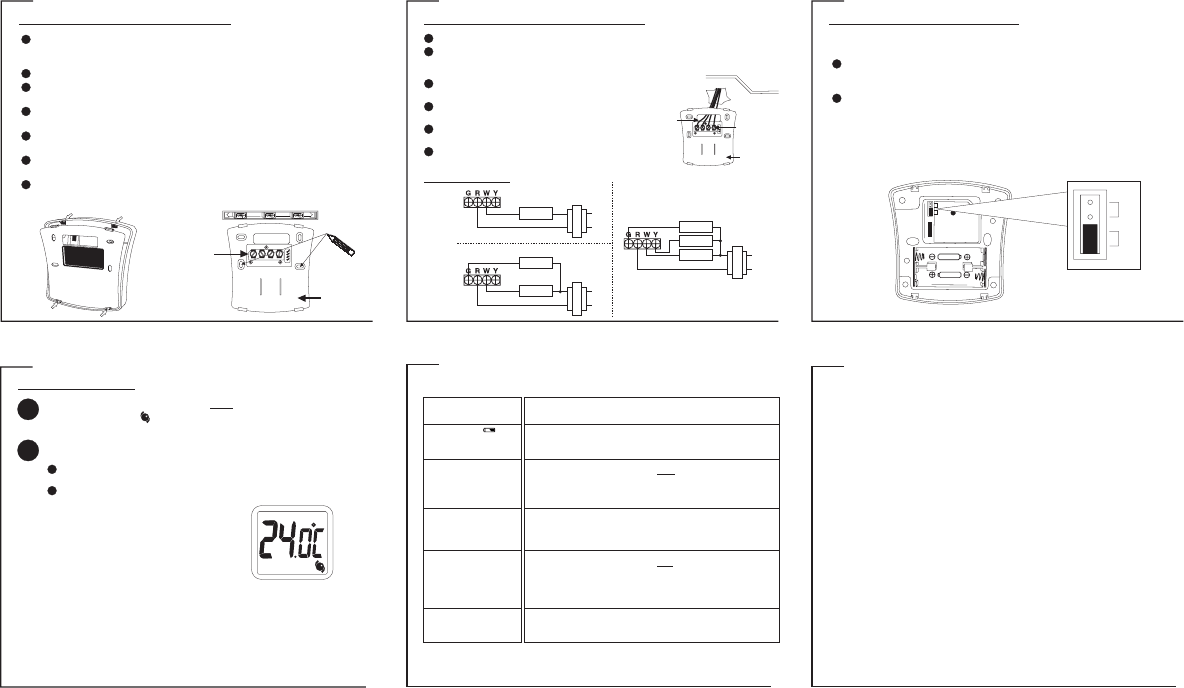
MOUNTING THE THERMOSTA
The back cover should be mounted with the large hole on the top.
Thread the existing wiring through the large hole from the back and set the back
cover flat on the wall.
Select two appropriate mounting holes and mark the locations with a pencil. If
necessary
Remove the back cover from the wall and drill two 3/16” holes in the marked screw
positions.
Insert the wall anchors into the holes completely I
tap-in lightly
Mount the back cover the wall. Make sure the terminals are
on the top-half of the back cover
Carefully separate the back cover from the thermostat by disengaging the 4 latches
found at the corners on the back of the thermostat. P
open with a screwdriver
INST
CONNECTING THE WIRES TO THE TERMINALS
Depending on your heating/cooling equipment, you may
need to connect 2 to 5 wires to the thermostat.
If your old thermostat has a ‘C’ wire, please wrap it with
electrician’s tape as it is not used with this thermostat.
If you have both an ‘R’ and ‘Rc’ wire, you may connect
them together to the ‘R’ terminal of the thermostat.
If you are unsure of the connections, or for new
installation, you may refer to the wiring diagrams below
Connect the previously labeled wires to the corresponding terminals, matching the
designations. Use a screwdriver to securely fasten the wires onto the terminals. Make sure
the wires do not short-circuit with other terminals.
WIRING DIAGRAM
Heating Relay
Heating Relay
Fan Relay
2-wire heating
4-wire heating/cooling
3-wire heating
INST
SETTING THE FAN OPERA
Depending on your home’s heating system, you may need to change the jumper setting for
the fan operation. The jumper is located above the battery compartment.
HG - Use this setting for gas or oil-fired furnaces. This setting allows the fan
operation to be controlled by the heating system; not the thermostat. This is the
correct setting for most systems.
HE - Use this setting for electric heating systems. With this setting, the thermostat
will turn on the fan immediately with the heating system.
The jumper is pre-installed in the ‘ ’ position as a factory default. So there is no need to
change the jumper if this is the correct setting.
HG
T
new position and push in fully
TURN OFF POWER to system at the furnace, or at the fuse/circuit breaker before wiring.
OPERA
TEMPERATURE SETTING
T right until it clicks to enter the temperature
setting mode. The “ ” icon will appear
the current SET temperature flashing.
once
1
T right to adjust to the desired set temperature.
NOTE: The display will automatically
return to the current temperature display
12 seconds after the choice has been
made.
2
The temperature can be set in increments of 0.5°.
The temperature setting range is from 5°C to 35°C (41°F to 95°F).
NOTE: There is a built-in delay action to protect the heating and cooling systems.
- When the heating system is ON, it will keep on running for at least 2 minutes even if there
is a change in the temperature setting.
- When the heating system is OFF can
come back ON.
- When the cooling system is ON, it will keep on running for at least 4 minutes even if there
is a change in the temperature setting.
- When the cooling system is OFF can
come back ON.
TROUBLESHOOTING
LIMITED ONE-
Disengage the latches to
separate the back cover
from the thermostat
LEVEL
+
+
Mark the locations
with a pencil
Metal terminals
Back cover
Wall
Back cover
Metal
terminals
Wires
HEAT
PROBLEM SOLUTION
P P P
LCD screen is blank.
The battery symbol ( ) is
flashing.
Heat will not come on.
Heat will not come on but the
“ ” icon is flashing.ON
Air conditioning will not come on.
Air conditioning will not come on
but the “ ” icon is flashing.ON
- Check if the batteries are installed correctly.
- Check if the batteries are fresh and of the correct type.
- Press the RESET key on the back of the thermostat above the battery compartment.
- This is an indication that the batteries are running low. Replace with fresh alkaline
batteries.
- Note: We recommend to have the batteries replaced at least once a year even if the battery
symbol is not flashing.
1) Check and ensure that the thermostat is set to the HEAT mode.
2) Check and ensure that the set temperature is t
3) Y The
built-in time delay to prevent undesirable on/off sequences.
4) After a 2-minute wait, the heating should now be on. Whenever the heating system is
running, the “ ” icon will be flashing.
higher
ON
1) Check if the furnace switch and/or pilot flame is turned on, as it may have been turned off.
2) Allow several minutes for the heating system to heat up and the fan to activate. Most
heaters will heat up the system for a short while before warm air can be ventilated by the
fan. Also check that the HE/HG setting is set correctly. (Refer to page 7).
3) If the heat still does not come on, check the wiring installation again. (Refer to page 6).
1) Check and ensure that the thermostat is set to the COOL mode.
2) Check and ensure that the set temperature is than the current (room) temperature.
3) Y The
thermostat has a built-in time delay to protect the air conditioner compressor from
undesirable on/off sequences.
4) After a 5-minute wait, the air conditioning should now be on. Whenever the cooling
system is running, the “ ” icon will be flashing.
lower
ON
1) Check if the air conditioning system’s main switch is turned on, as it may have been
turned off.
2) Wait several minutes for the air conditioning system to activate. If the air conditioning still
does not come on, check the wiring installation again. (Refer to page 6).
UPM warrants this product, excluding battery, to be free from defects in the materials or workmanship, under normal use and
service, for a period of one year
If, at any time during the warranty period, the product is defective or malfunctions, UPM shall repair or replace it (at UPM's
discretion) within a reasonable period of time.
If the product is defective,
(i) return it, with a dated proof of purchase, to the retailer from which you purchased it, or
(ii) package it carefully, along with a dated proof of purchase and a short description of the malfunction, and mail it, postage
prepaid, to the following address:
UPM Marketing Inc.
Return Goods
Unit 10B - 250 Shields Court
Markham, Ontario
L3R 9W7
This warranty does not cover removal or reinstallation costs. This warranty shall not apply if it is shown by UPM that the defect or
malfunction was caused by damage which occurred while the product was in the possession of the consumer
UPM's sole responsibility shall be to repair or replace the product within the terms stated above. UPM SHALL NOT BE LIABLE
FOR ANY LOSS OR DAMAGE OF ANY KIND, INCLUDING ANY INCIDENT
DIRECTL
THIS PRODUCT Some states do not allow the exclusion or limitation of incidental or consequential damages, so this limitation
may not apply to you.
THIS WARRANTY IS THE ONL THE DURATION OF ANY IMPLIED
WARRANTIES, INCLUDING THE WARRANTIES OF MERCHANT
HEREBY LIMITED TO THE ONE YEAR DURATION OF THIS W Some states do not allow limitations on how long an
implied warranty lasts, so the above limitation may not apply to you.
This warranty gives you specific legal rights, and you may have other rights which may vary from state to state.
If you have any questions concerning this warranty, please write to:
UPM Marketing Inc.
Customer Service Department
Unit 10B - 250 Shields Court
Markham, Ontario
L3R 9W7
Or call 1-888-GO-TO-UPM (1-888-468-6876), Monday to Friday
(1)
Fan Relay
Heating Relay
Cooling Relay
HG
HE