CLEANINGANDMAINTENANCE
Besidesoccasionalcleaningandbatteryreplacement,thevoltagetesterismaintenance-free.
Thevoltagetestermustbedisconnectedfromalldevicesundertestbeforecleaning.
Aftercleaning,allowtheproducttodrycompletelybeforeusingitagain.
Nevertrytoopenthehousing,apartfromthebatterycompartment.
Checkthetechnicalsafetyofthevoltagetesterregularly
• ifthedeviceorheconnectingcableisvisiblydamaged
• afterprolongedstorageunderunfavourableconditions
• afterextraordinarytransportstress
Theoutsideofthedeviceshouldbecleanedwithasoft,dampclothorbrushonly
agentswhichcoulddamagethehousingorimpairoperation.
DISPOSAL
theendofitsservicelife,pleasedisposeofit,accordingtothecurrentstatutoryrequirements,atyourlocal
collectingsite.Itisprohibitedtodisposeofthedevicewithdomesticwaste.
Disposalofusedbatteries!
Y
householdwasteisprohibited!
ofdisposalwithdomesticwaste.Thesymbolsoftherelevantheavymetalsare:Cd=Cadmium,Hg=Mercury
Pb=Lead.Y
wherewherebatteries/accumulatorsaresold.
Thusyoufullyourstatutoryobligationsandcontributetotheprotectionoftheenvironment!
TECHNICALDA
Generalinformation
V 12,24,36,50,120,230,400,690V
V 12-690V
ResolutionLCD 0.1V(12-300V),1V(>300V)
Polarityindicator +,-,+/-(AC)
IndicatortoleranceLCD ±(3%+5counts)
IndicatortoleranceLED accordingtoEN61243-3
V automatic
Signal >38V
Displaydelay <1sLED
Frequencyrangef DC,16...400Hz
Powerinput approx.2.1Wat690V
MaxtestcurrentI <3.5mA
WarningindicatorLED >50V/AC,>120V/DC
Measuringtime/cycle max.30seconds
Resttime 240seconds
LED/LCDindicatorfrom >10V
Powersupply 2x1.5V(AAA/LR03)
Batterypowersupply approx.80mA
T -15to+55°C
Storagetemperature -20to+70°C
Rel.Humidity max.85%,non-condensing
Measurementcategory CA
Pollutiondegree 2
Operatingaltitude max.2000maboveN.N.
Protectiontype IP64
Rotatingelddirectionindicator onlyongroundedthree-phasesystems!
V 120-400V/AC
Frequencyrange 50/60Hz
Continuitytest
T 0-500kΩ(+50%)
Overvoltageprotection 690VDC/AC
Single-polephasetest
V 100-690V/AC
Frequencyrange 50/60Hz
Legalnotice
TheseoperatinginstructionsareapublicationbyConradElectronicSE,Klaus-Conrad-Str.1,D-92240Hirschau(www
processingsystemsrequirethepriorwrittenapprovalbytheeditor.Reprinting,alsoinpart,isprohibited.
©Copyright2014byConradElectronicSE.
G
•
doesnotgetpinchedordamaged.Thereisonlyonepositionforthebatterycompartmentcovertomatchthedevice.The
groovemustbelocatedontheright.
Batteryreplacementisnecessarywhenthelevelindicator(8)isnolongerilluminatedduringthefunctiontest,orthebattery
replacementsymbolappearsontheLCD,orifyoucannothearthesignalsoundanylonger,whenthecontactsofthetwo
probes(4and6)areincontact.
whenthetestvoltagereaches50V/ACor120V/DC.Donotevertouchthemeasuringcontacts,ifthis
indicatorison.
Operationwhilethebatterycompartmentisopen,isnotpermitted.
T
longerperiod.Forthesamereason,werecommendthatyouremoveatbatteriesimmediately
Compatiblealkalinebatteriescanbeobtainedwiththefollowingordernumber:
Ord.no.652303(2pcs.Pleaseorder1xunit).
Onlyusealkalinebatteries;theyarehigh-performanceanddurable.
MESUREMENTPOINTSILLUMINA
TheVC-55hasabattery-operatedmeasuringpointillumination.
Pressbutton(15)toturnilluminationonandoff.Thelightisonforabout130secondsanddisappearsautomatically
PERFORMINGTESTSANDMEASUREMENTS
Thetwo-polevoltagetesterconsistsofthetwoprobes(4and6),aconnectingcable(18)andtheindicatorpanel.
Alwaysholdthevoltagetesterinaway
adverselyaffectedbystronglight.
ForDCmeasurements,theprobetipL2+(6)isthepositivepole,andtheprobetipL1-(4)isthenegativepole.
TheVC-55willautonomouslyturnonwhentheteststarts(entrylevel>10V),andwhenthetesthasbeencompleted,itturns
off.
aknownvoltagesource(mainsvoltage230V/AC,forexample)rst,andchecktheaccuracyofthe
readouts.Intheeventofoneormoreindicatingranges(8)fail,donotusethevoltagetester
sionthevoltagetester
usedwhenworkingonsystemswithdangerouselectricalvoltage.
of240minutesatleast,hastobemaintained.
Thefollowingmeasurementfunctionscanbeconducted:
a)T
Alwaysholdthevoltagetesterbythehandlesdesignedforthispurpose(1and16).Neverreachbeyondthetactilebarrierof
thegrip(5and13).
Guidethetwoprobetipsontothemeasurementpointstobetested.Thevoltagerangeisshownonthelevelindicator(8)and
thepresentmeasuringvoltageisshownontheLCDdisplay
Thelightindicators(+)and(-)showthetypeofvoltageandthecorrespondingpolarity
litatthesametime,alternatingcurrent(AC)ispresent.PolarityisonlyindicatedbymeansofthetwoLEDs.
Atavoltageofabout38V/ACor100V/DCasignalsoundisproduced.Therotatingeldindicator“L”and“R”mayash
duringmetering.Thisisatechnicalissueandiswithoutsignicanceorimpactonthemeasuringprocess.
ThetwoprobetipsL1undL2canbeconnectedtooneanother
handlegripbarrierofprobetipL1(5).
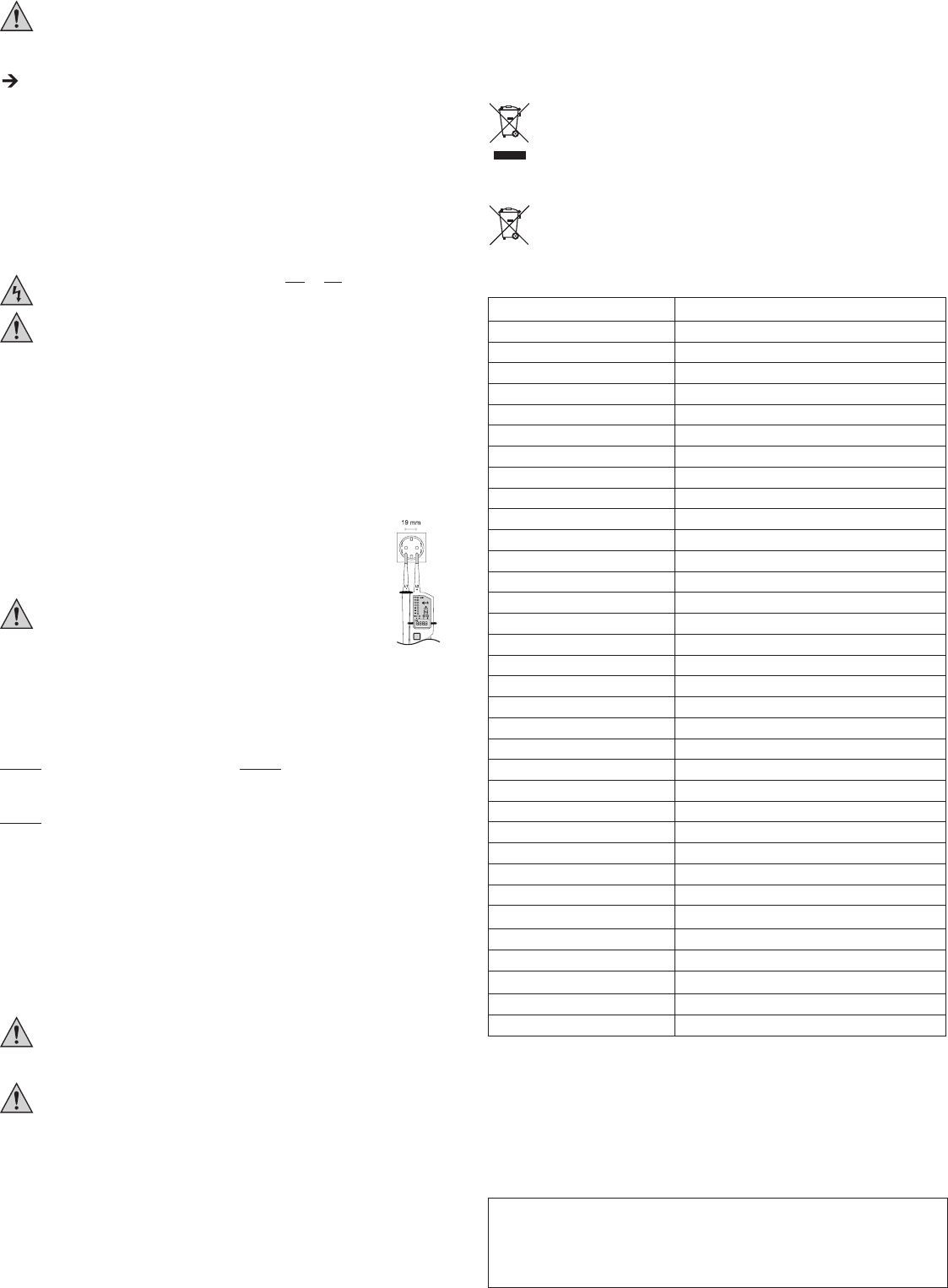
Thedistancebetweenthetwoprobesis19mm,whichcomplieswiththestandardizedcontactgapfor
EUandsafetysocketoutlets.
Inaddition,establishingcontactinsidetheoutletsismadeeveneasierwhentheincluded4mm
adapterscrewsareused.Thatway
Makesurethatyourhandremainswithinthegriparea(16)ofprobetipL2andthat
youdon’tcoverthedisplay
b)Rotatingeldindicator
VC-55showstherotatingelddirectionofproperlygroundedthree-phasesystems(withbatteriesonly).Thevoltagetester
detectstheorderofincreasingphasestogroundpotential
Holdthevoltagetesterbythehandles(1)and(16)provided.Nevertouchthedevicebeyondthehandleends.
Connectthetwoprobestothemeasuringpointsthatyouwanttomeasure.
TheprobeL1(4)correspondstotheoutercable(phase)L1.
TheprobeL1(6)correspondstotheoutercable(phase)L2.
Theavailablevoltagerangeandthephasesequenceisrepresentedonthedisplay
Theilluminatedindicators(12)showtheapplicablerotatingelddirection(L=leftturning/R=rightturning).
Example1: Example2:
ProbetipL1tooutercableL1, probetipL1tooutercableL2,
ProbetipL2tooutercableL2, probetipL2tooutercableL3,
Thecorrecteldrotation“R”isdisplayed Thecorrecteldrotation“R”isdisplayed
Example3:
ProbetipL1tooutercableL2,
ProbetipL2tooutercableL1,
Oppositephasesequence“L”isdisplayed
c)Continuitytest
Whenbatteriesareinserted,theVC-55canbeusedasacontinuitytester
Holdthevoltagetesterbythehandles(1)and(16)provided.Nevertouchthedevicebeyondthehandleends.
Checkfunctionbeforeyourstartmetering.
Connectbothprobetipstooneanother
Ifthisisnotthecase,replacethebatteriesasdescribedunder“Inserting/ReplacingtheBatteries”.
Thecontinuitytesterindicatesaresistanceofabout0-500kΩ(+50%)ascontinuity
d)Single-polephasetest
Whenbatteriesareinserted,theVC-55canbeusedasasingle-polephasetester.
Holdthevoltagetesterbythehandles(1)and(16)provided.Nevertouchthedevicebeyondthehandleends.
absenceofvoltagemustberecheckedusingthedouble-polemeasuringmethod.Observetheregula-
tionsregardingworkwithelectricalsystems.
ContactprobetipL2withthemeasuringpointtobetested.ProbeL1hasnocontact.
Ifanalternatingvoltage>100Vispresent,theindicator(10)lightsupandasignalsounds.
staticelds,goodinsulationetc.).However
thatvoltageisabsent.