D
1
2
E
F
A
G
30-33 cm
zum Boden
Die fahrradseitigen K
für den bleibenden Anbau gedacht und
bestehen aus den K
Polygoneinsätzen für Schnellspanner
oder V
Bei Montage an ein Fahrrad mit V
achse werden die beiden Mutt
und rechts abgenommen, bei Schnell-
spannachsen wird der Schnellspanner
herausgezogen. Die für Ihr Fahrrad pas-
senden Polygoneinsätze D so einse
dass die Rastnasen in die Radaufnah-
me zeigen. Welchen P
was: T
Schnellspannachsen, je nach Rahmen-
form. (Bei Schnellspannachsen können
Sie die “Dickeren” v
Anbauteile den Einsatz der “Dünnen”
verhindern.) Die beiliegenden Einsätze
passen für normale Schnellspannach-
sen und für die meisten V
V
Shimano V
gesonderte Polygoneinsätze bei uns mit
Aufpreis best
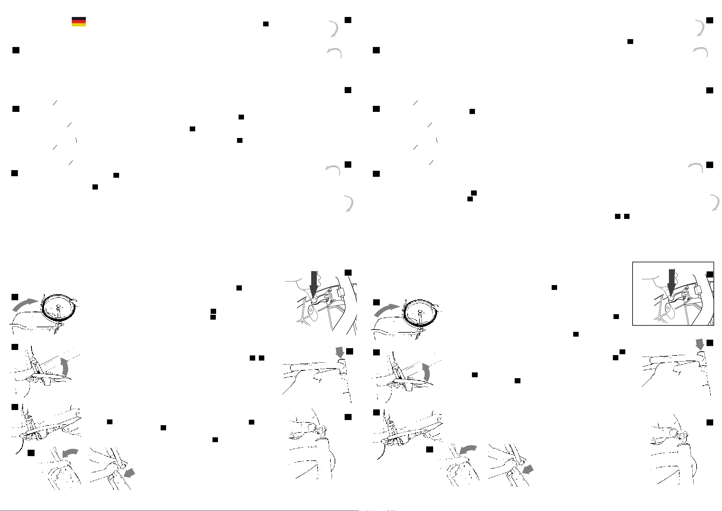
Die Rastnasen sollten annähernd spiel-
frei sitzen 1 . Setzen Sie die Koppelau
nahme E entsprechend Ihrer Radgröße
3 so auf, dass die AufnahmerF
in einer Höhe von etw
Boden positionier
die Radmuttern nach der Beilagscheibe
aufsetzen, bei Schnellspannachsen
die Schnellspanner G einsetzen und
wiederholt f-
Anbauanleitung
K
Fahrradseitig
aufnahmen auf spielfreien Sitz prüfen.
Die Reihenf 2
dargestellt. Die mit A gek
Scheiben auf beiden Seiten einsetzen.
Achtung: Unbedingt die Beilagscheibe
A unterlegen, ansonst
Garantie und Gewährleistung für die
K
Sie darauf, dass das Gewinde des
Schnellspanners mindestens 5mm in
die Mutter des Schnellspanners ragt,
sonst verwenden Sie einen verlängerten
Schnellspanner (erhältlich bei uns unter
Best.Nr KU.03.330.00).
Zum Ankuppeln beide Griffstücke dur
Drücken auf die F
und nach innen drehen 4 . K
auf K
5 . Zum V
aussen drehen, bis die Feder
und sichtbar einrasten 6 .
Kontrollieren Sie bei den erst
Fahrten den f-
spanners oder der Achsmutter und
spannen oder ziehen Sie diese gegebe-
nenfalls nach. Prüf
T
der Koppelaufnahmen.
Bei lockerem Sitz der K
kann es zu einem einseitigen V-
schen der Deichsel kommen, w
einer Schädigung der V
führen kann!
3
4
5
6
Ihr Weber monoporter ist ein Einrad-
nachläufer mit besonderen Mer
hierzu gehören die 2-seitige Kupplung,
das geringe Gewicht, das handliche
Packmaß, die sekundenschnelle
Klappfunktion und die Federung.
Der monoporter ist kein Tieader für
Schwerlast
T
dung auf guter W
schlechten W
reduzierung auf max.
um Fahrrad und Anhänger zu schonen)
hervorragendes Fahrverhalten zeigt.
Bitte acht
monopor
Schwerpunkt der Ladung, d. h. schw
res Ladegut muss hinten unt
Ladeäche liegen; leichte, gr
T
Aufbau Federschwinge
Legen Sie den monoporter mit der
Ladeächenoberseite auf den Boden
und schwenk
der Schwinge bis zum Anschlag nach
außen 7 . Schwenk
Spannbügel mit dem Federpak 8
über die Gegenplatte der Schwinge.
Das Federpak
an der K
anliegen. Danach den
Anbauanleitung
Monoporter
Spannbügel kräftig gegen den Druck
der Feder bis an das Schwingenr
drücken, sodass das F
K 9 .
Aufbau Plattform
Die Plattform wir-
schwenkt 10 und mit dem Klemmhebel
verriegelt 11 . Der Hebel rastet nach
kräftigem Druck mit dem Daumen nach
unten, mit einem deutlichen „Klack“
ein. Bitte beac
Hebel nur anheben bis er ausrast
nicht weit Ihr monopor
noch an Ihr Fahrrad anzuk
damit fahrbereit. Siehe Abb. 4 - 6 .
Kontr
mehrmals den fest
fahrradseitig montierten Koppelaufnah-
men. Spannen Sie gegebenenfalls Ihre
Schnellspannachse nach.
Aufbau Gabel
Die Gabel der Zentraldeichsel wird auf
den Gelenkzapfen des Hauptrahmen-
rohrs so aufgesetzt, dass die A
monopor 12 .
Danach V
und mit beiliegendem Inbusschlüssel
festziehen 13 .
Achtung! Der T
dem monoporter ist verboten!
7
8
9
11
12
13
10
D
1
2
E
F
A
G
The par
for permanent installationon the dr
pouts of your bik
for the horizontal f
the trailer
aquick release axle or f
shims. The par
both sides of your bicy
At the full axle syst
hav
At the quick release axle syst
hav
lease. The polygons serves as a security
against torsion. They are t
base-par
points into the wheel-absorption. (see
picture 1 )
Which polygon f
full axle system, type 1 and 2 f
release axles. Y
one, if attachment parts impede the
installation of the “thinner” one. The
enclosed polygons t f
release axles and for most full axles. W
hav
with a diameter 1
as the Shimano T
Place the attachment on the rear
dropout 2 The
wards 3 . The absor
be 30-33 cm form the gr
forget the shims. A
axle systems against the wheel-nuts. A
quick release axle systems insert the
Mounting
Instructions
attachment bikesided
quick release sk
shut tightly
tachment to the bik
backlash. The correct order of installing
the par 2
. The shims, marked with A, ha
tted on both sides.
Att
otherwise the warranty for the mono-
por
its function cannot be warrant
claims will not be accepted b
T
the axle nut min. 5 mm or 8 rotations.
Otherwise use a longer quick release
axle (you can get it fr
Number KU.03.300.00 ). After your rst
outings or rides with the trailer check
the quick release axle or the axle nuts
that ev
necessary ajust the nuts. On tour
adives that your check the com
system frequently
monopor
cause a one-side shift of the drawbar
This can cause damage of the polygon!
T
the suspention pins on the drawbar
down and turn the handles in
Gently press the drawbar ont
attachment ttet t
as you ha
handles outwards. Y
attached to y 4 - 6 )
3
4
5
6
Y
wheel-trailer with distinguishing marks.
Among them are the two-sided hitch,
low weight, handy f
ments, the Monoporter folds down a
matter of seconds and it e
suspension system. The monoporter
isn´t a at-bed-trailer for hea
instead it is a sporty transpor
the possibility to carry up to 25 kg on
good roads, ho
15kg on bad road conditions.
Installation motion link
Put the monoporter with the sur
the baseplate on the gr
the wheel with the motion link to the
stop out 7 . Pass the clam
with the suspension package 8 around
across the count
link. Let the suspension package la
the plastics moulding. Then push the
clamping lev
the suspension on the motion link tube.
Monoporter
Instructions
The suspension package has to click
into the sock
9 .
Fork Installation
Ensure that the central-shaft on the
main-frame tube, with the inscription
“monopor 12 Put
on the locking cap and fasten it with
the tool, which is locat
baseplate 13 .
Platform Installation
Swing the baseplate 90° ar 10 and
bolt it with the clamping lev 11 .
it in with your thumb until the le
snaps in with a loud “Clack”. Check that
ev
Monopor
Attention!
Do not transport children! The monopor-
ter is not designed f
on, the absence of a seat and seatbelts
would endanger your children!
Enjoy your monoporter!
7
8
9
11
12
13
10
30-33 cm
from ground